This project explains how to wire a closet light with Wiremold metal raceway to extend power from an existing electrical outlet in this installment of How To Build a Basement Closet. This project is continued from Part 4.
Extend Power from an Existing Wall Outlet
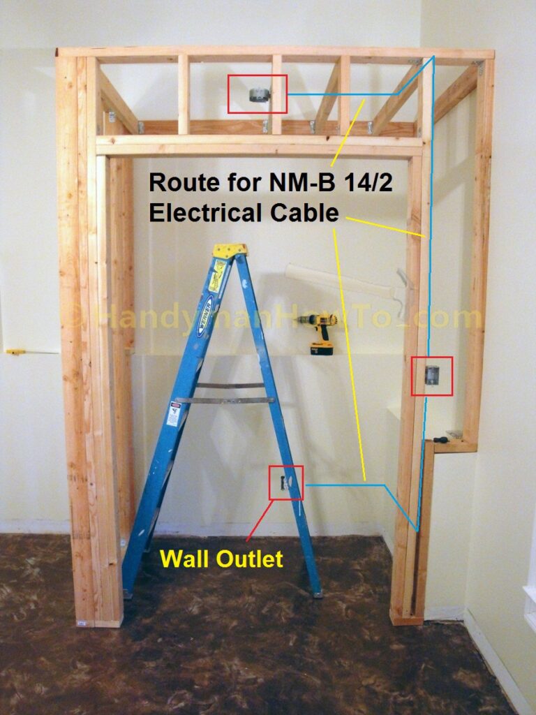
120VAC power will be extended from the wall outlet inside the closet to the light switch and closet light as illustrated in this photo using Wiremold® 700 series metal surface raceways and Wiremold receptacle box fittings with Romex® NM-B 14/2 electric cable.
Electrical Building Permit
Wiring a new branch circuit requires a building permit and electrical inspection to ensure all work complies with the National Electric Code© (NEC) which are incorporated into your local Building Codes. I filed for a Building Permit to cover the closet framing and wiring. If in doubt, contact your local Building Dept. for permitting and inspection requirements.
If you are uncomfortable or uncertain about working with electricity and wiring, please hire a licensed electrician.
Wiremold 700 Series Surface Wiring Materials
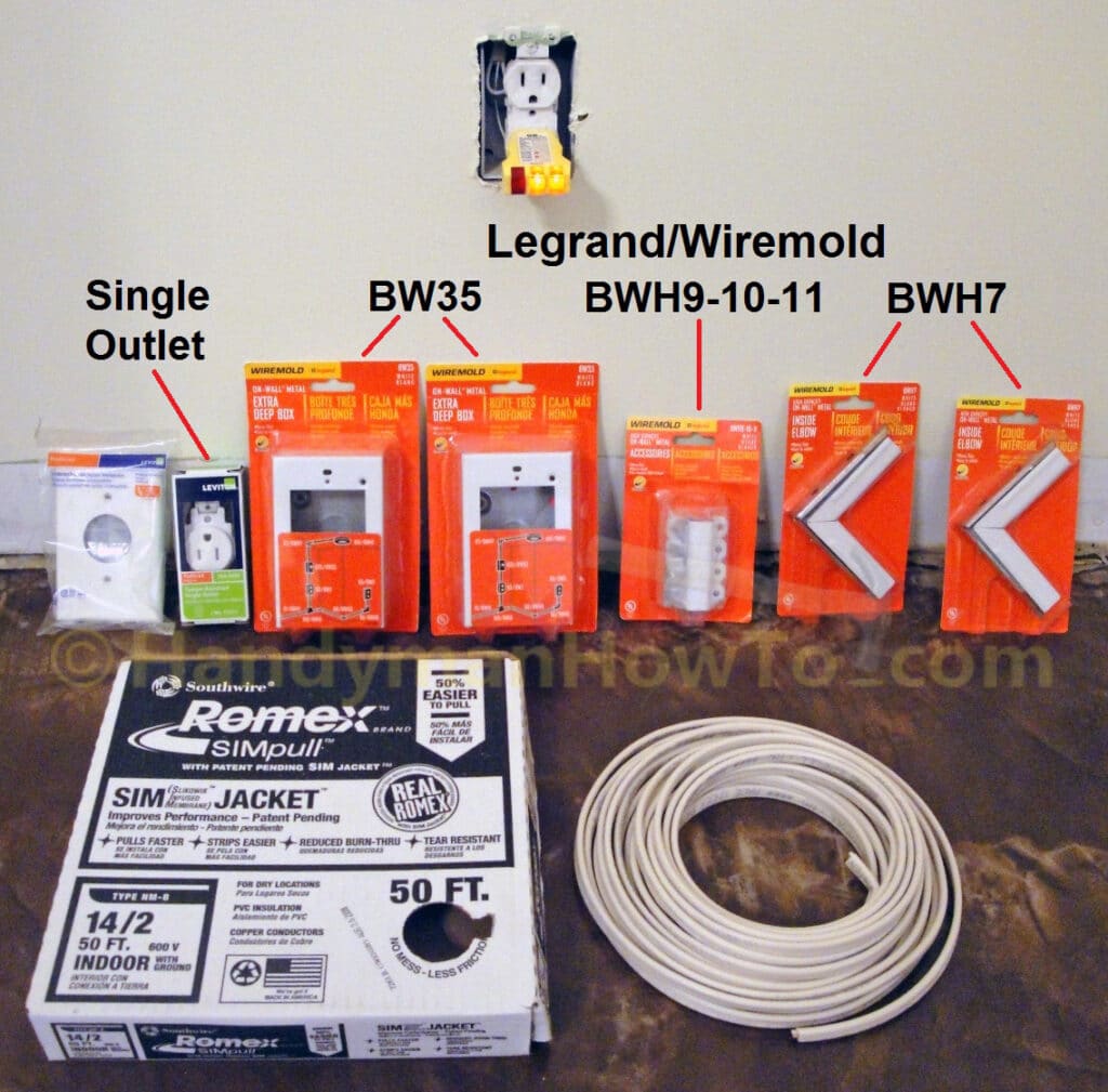
Based on the simple wiring plan in the above photo, I created a list of Wiremold components to extend power from the existing wall outlet to the closet ceiling light:
- Leviton unbreakable nylon single outlet wall plate.
- Leviton Tamper-Resistant Single Outlet rated for 15 Amps, 125 Volts.
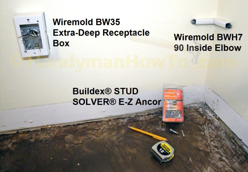
Because people have a tendency to overload wall outlets, I opted to install a single outlet instead of a dual outlet. I also figured that a single outlet in the closet would be sufficient. This is just my personal preference. - Wiremold On-Wall® Metal Extra Deep Outlet Box, part # BW35
- Wiremold Metal Raceway Accessory Pack, part # BWH9-10-11
- Wiremold Metal Raceway Inside Elbow, part # BWH7
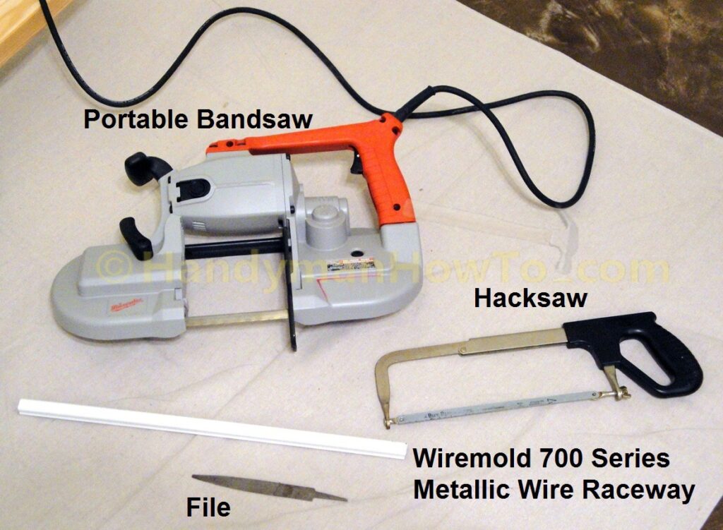
- Wiremold 700 Series Small Raceway metal channel, 10 foot length (not shown in the photo below)
- Romex® NM-B 14/2 electric cable
14 gauge, 2 conductor (hot & neutral) wires plus the ground wire
Other miscellaneous electrical wiring supplies are:
- Halex 3/8 in. 2-Piece Clamp Connectors (5-Pack).
- #10 Grounding Screws for metal electrical boxes.
- Wire Nuts for 14 and 12 gauge wire.
- #6-32 screws to fasten the Wiremold outlet box the wall electrical box.
To put the following Wiremold installation steps into perspective, the finished job is shown in the following photo. Power is extended from the existing wall outlet around the inside corner of the closet wall into the newly constructed 2×4 wall to the light switch and closet light:
Wall Outlet Power Extension Wiring Diagram
The following Wiremold wiring diagram illustrates the electrical devices and wiring connections to extend power from an existing wall outlet to the ceiling closet light.
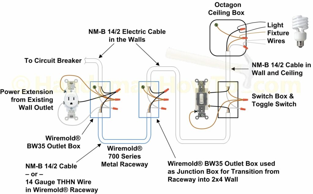
Recall that I chose to replace the original dual wall outlet with a single outlet, however a dual outlet may be installed.
Wiremold: NM-B versus THHN Wire
Single conductor stranded THHN type wire is normally installed in Wiremold raceways because THHN wire is more flexible for pulling and can take sharper bends around corners.
Solid conductor NM-B type cable can be used in Wiremold raceways in compliance with the NEC 310.11 for proper cable and conductor marking, only if the outer insulation jacket is NOT removed. This is because the outer jacket on NM-B cable is marked while the individual conductors are not marked
NM-B cable is much stiffer than THHN wire, therefore the full length of NM-B cable required to reach the next junction box must be pushed or pulled through each section of Wiremold channel as it’s installed.
I chose to use NM-B cable since it’s what I have on-hand and saved the cost of buying THHN wire.
Wiremold Wall Outlet Power Extension
Watch the Wiremold installation video on YouTube.com to familiarize yourself with the system.
Be absolutely certain to shutoff the power at the circuit breaker panel before starting work on the wiring. Failing to do so can cause injury and/or death. Always hire a licensed electrician if in doubt.
Verify the power is off with an outlet tester or voltage detector. I always plug the outlet tester in first to verify the outlet is powered and correctly wired (it also shows the tester is working!) then shutoff the circuit breaker. The outlet tester lights are all Off indicating the electricity is Off.
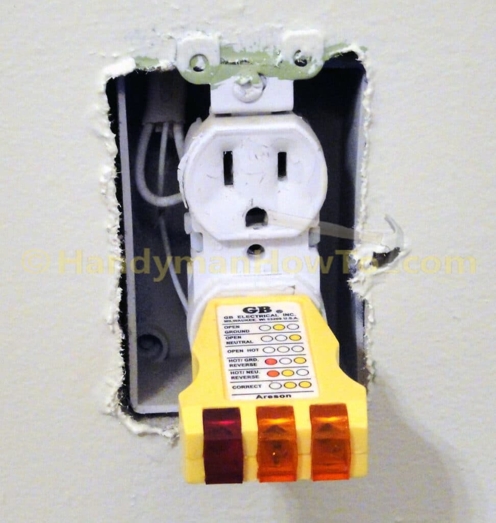
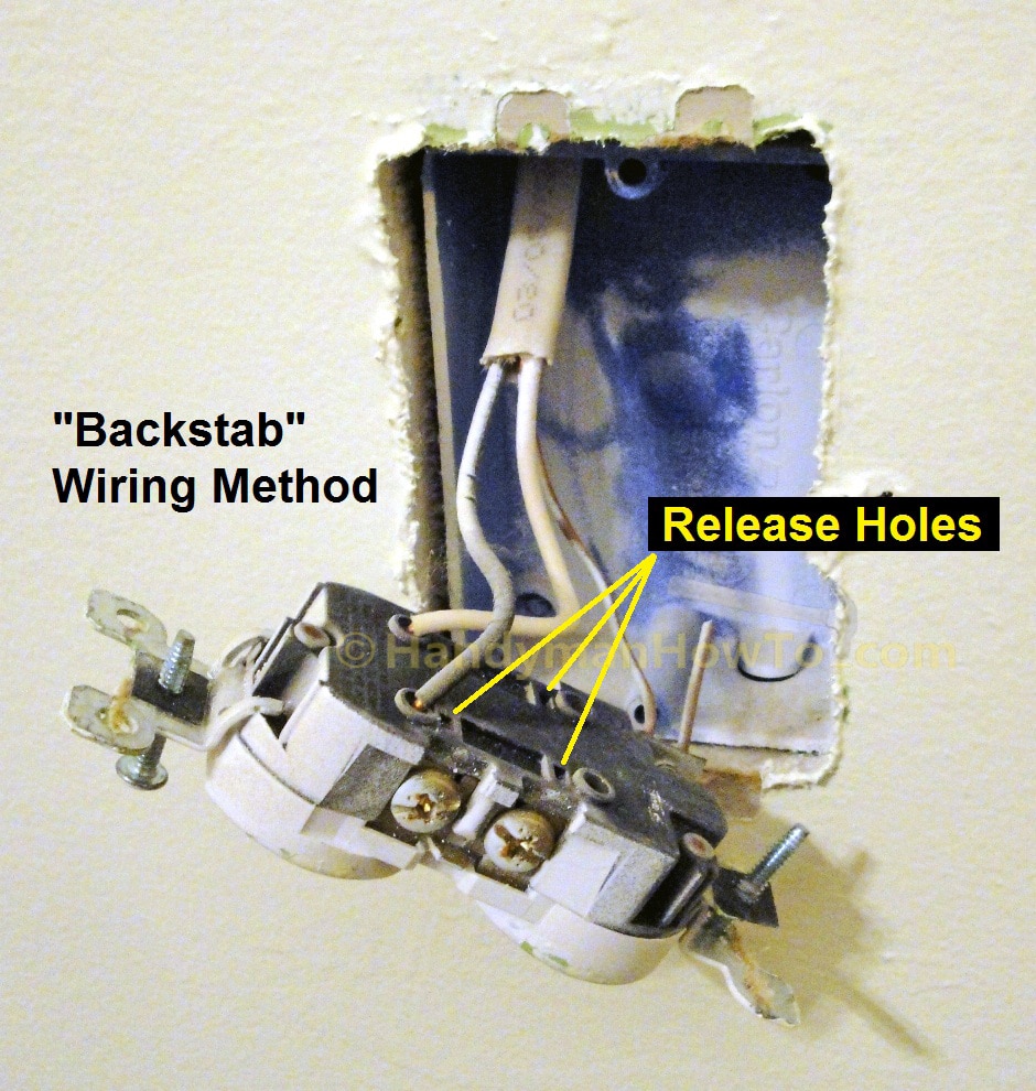
Remove the receptacle mounting screws to release the outlet from the wall box. Couple of notes here:
- The old outlet is wired using the “backstab” method. Press the tip of a very small screwdriver into the release holes to pull the wires out.
- The original electrician just met the required 3 inches of wire extending beyond the wall box. The wall box is very shallow because the concrete foundation wall is behind the electrical box, which has been furred and finished with drywall.
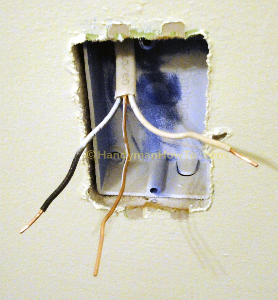
NM-B 14/2 wires after removing the electric receptacle:
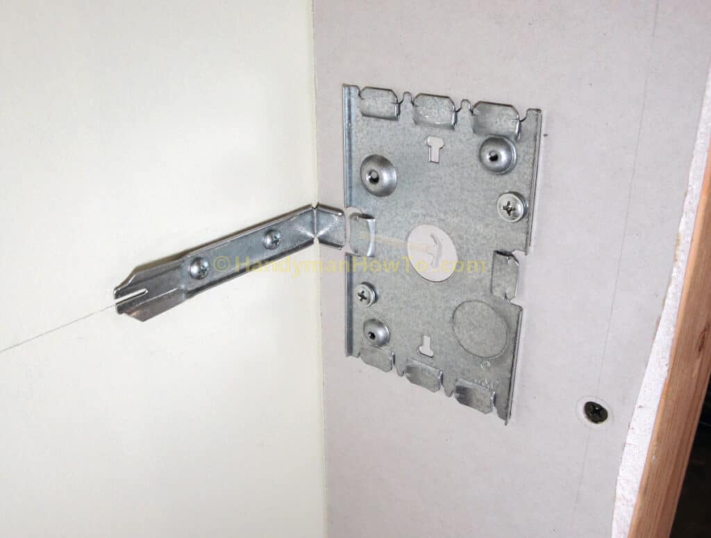
- The NM-B 14/2 wires are fed through the center of Wiremold BW35 Outlet/Receptacle box back plate, then the back plate is leveled, then fastened to the plastic wall box with two screws. Wall box mounting screws are not included with the BW35 Wiremold outlet box, so you must provide your own.
- The NM-B 14/2 wires are fed through the Halex 3/8 in. 2-piece clamp connector. The clamp connector acts as a bushing to protect the wires from the sharp edges of the back plate hole.
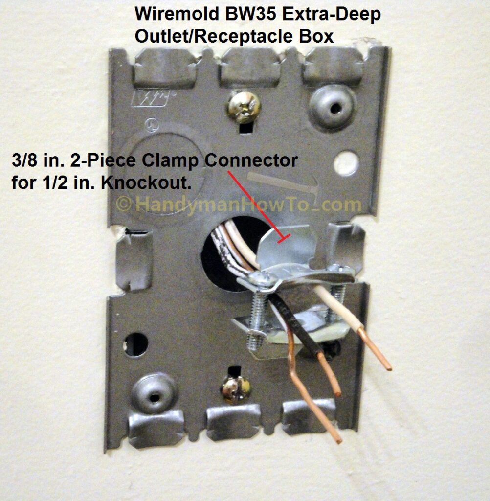
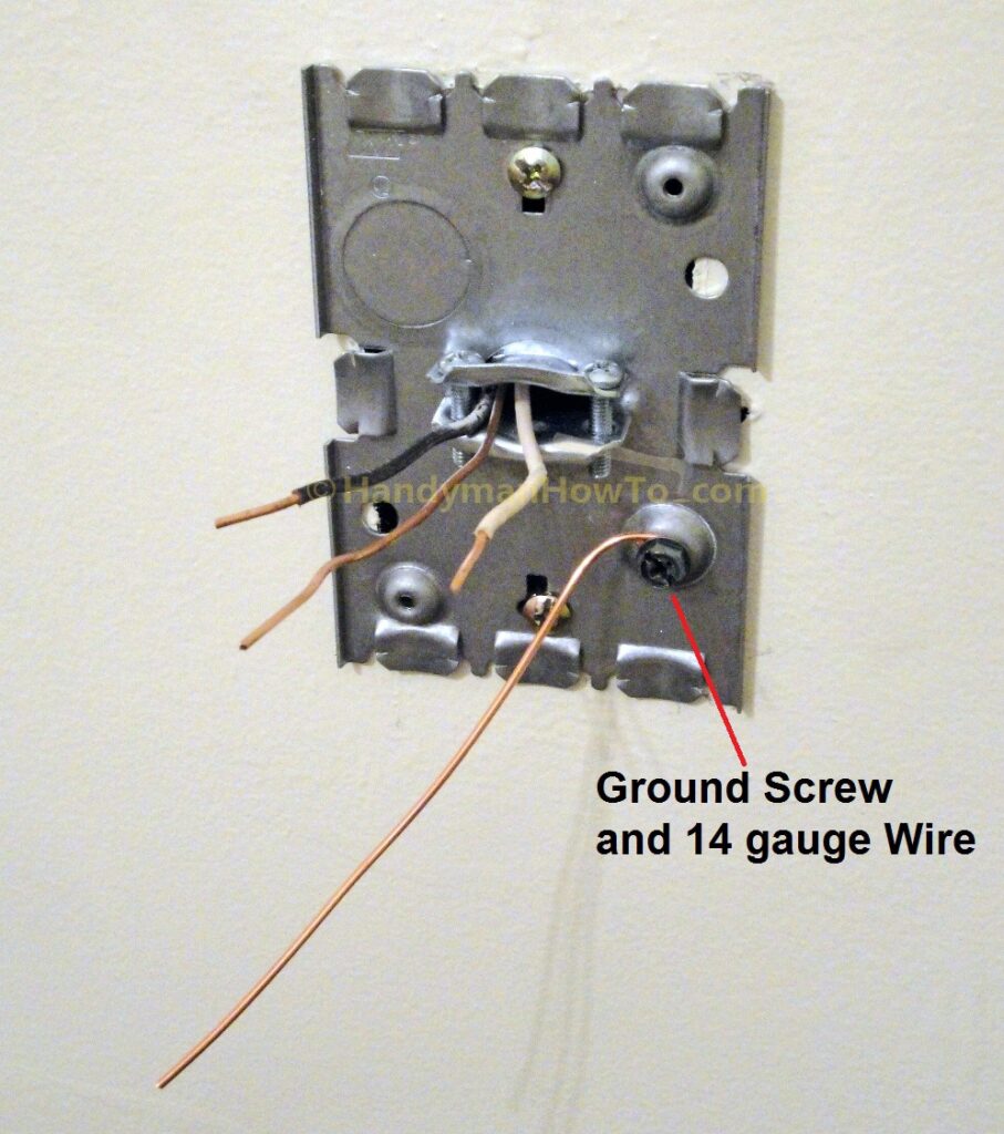
The “wings” of the Halex clamp connector mount inside the Wiremold back plate. Don’t tighten the clamp screws yet, this will be done later. Next, a 6 inch length of 14 gauge copper ground is installed with a #10 ground screw in the metal dimple. Loop the ground wire around the ground screw, then tighten the screw. The ground screw and wire are required by the Building Code to ground the outlet box.
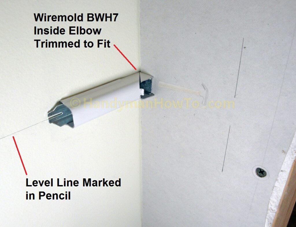
A horizontal level line is drawn on the wall with the carpenter’s level from the center of the Wiremold BW35 receptacle box to the corner and right wall. The twist-out on the right side of the receptacle box cover is removed with a pair of pliers. Note the twist-out is scored for the Wiremold 500 (small profile) and 700 (larger profile) metal channels. I’m using the larger size Wiremold 700 raceway and removed the whole twist-out the outlet box.
The Wiremold 90 degree inside elbow BWH7 is marked and mounted next with Buildex® STUD SOLVER® E-Z Anchors to the drywall.
The the distance between Wiremold receptacle box and inside elbow is measured, then add 3/8 inch to both ends (or 3/4 inch total) because the raceway has a slot that connects to the tongue on the outlet box and elbow. A standard 10 foot section of Wiremold 700 series raceway is clamped to the workbench and the measured section is cut. The Wiremold steel channel can be cut with a hacksaw, but why not bring out the big toy and cut it with the Milwaukee Tools portable band saw? (I’m always looking for excuses to buy tools. The band saw cuts through the raceway like it was butter.) Debur the cut with a file per the Wiremold metal raceway installation instructions.
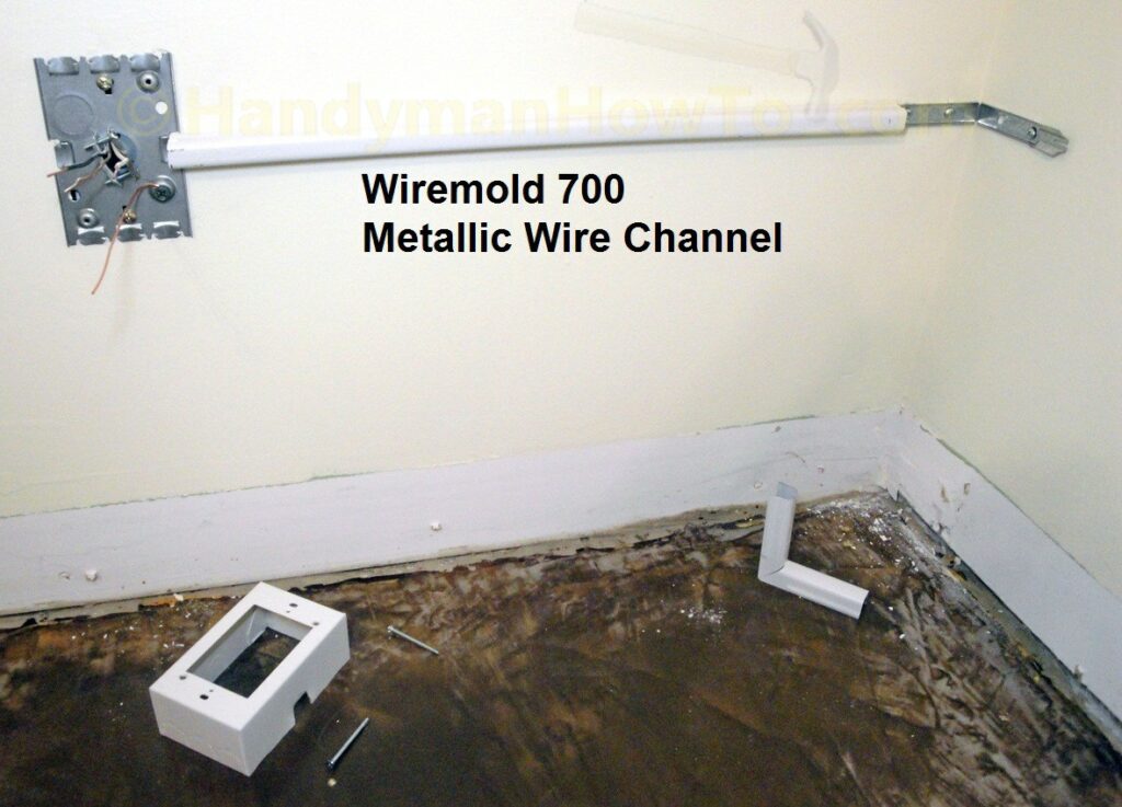
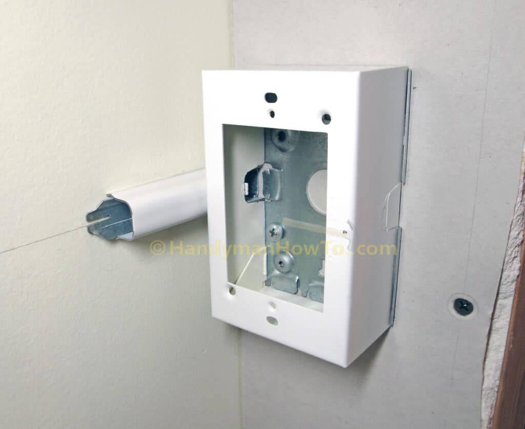
The Wiremold 700 metal channel fits on the mounting tabs of the receptacle box back plate and elbow. Wiremold is intended to be installed one item at a time working in a linear fashion and you may have to unscrew the inside elbow to mount the steel channel. The NM-B 14/2 cable will be installed after I’ve fitted all the Wiremold components.
The 2nd Wiremold receptacle box will mount inside the wall by the closet door. The center wiring hole in the back plate is positioned so it’s centered between the wall studs to run the NM-B cable into the wall. I measured and sawed (i.e. shortened) another piece of Wiremold 90 degree inside elbow to fit the box.
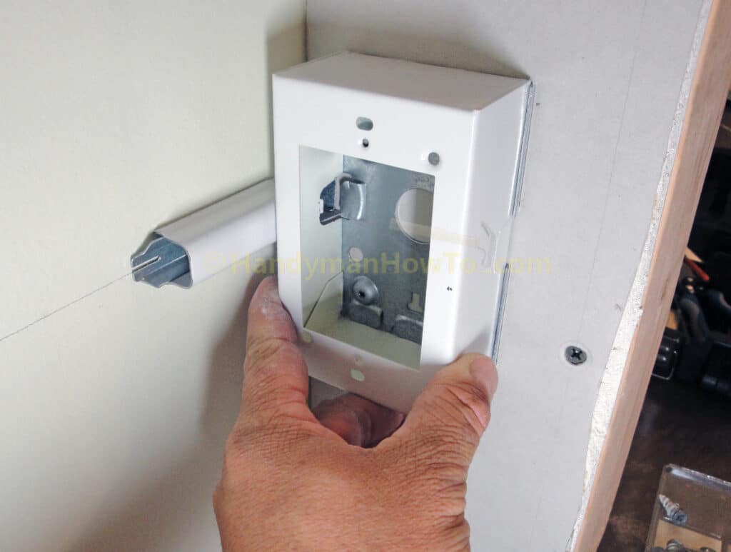
Detail of fitting the Wiremold BWH7 inside elbow:
The Wiremold receptacle box back plate is mounted to the 2×4 wall studs with Simpson Strong-Drive wood screws. I used the EZ Ancors to mount the elbow to the drywall.
Checking the final fit of the inside elbow and receptacle box after mounting with screws:
The wiring rough-in explained in the next part of this project.
Thanks,
Bob Jackson