How to Wire an Electrical Outlet Under the Kitchen Sink: Wire the NM-B 12/2 cable for the branch circuit to the Ground Fault Circuit Breaker (GFCB).
This project is continued from How to Wire an Electrical Outlet Under the Kitchen Sink – Part 6.
Since I’ll be working in the main circuit breaker panel, I shutoff the electricity to the house at the 150 AMP main service disconnect on the outdoor electric meter box. Do not attempt to work on the circuit breaker panel unless the electricity is OFF because you can be shocked, burned or maimed. If in doubt, hire a licensed electrician.
Install NM Cable Clamps on the Circuit Breaker Panel Knockouts
Before I wire in the new NM-B 12/2 branch circuit for the under sink outlet for the instant hot water dispenser, I need to take care of a small issue: no cable clamps are on several NM-B cables entering the main panel. Cable clamps are required by the National Electrical Code (NEC) to protect the cables from the sharp edges of the knockouts on steel panel box:
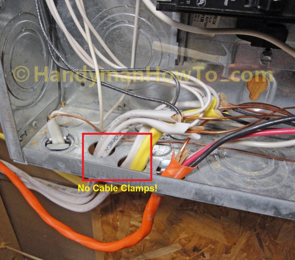
The cables serve wall outlets and lights in the finished basement – work that was done by the prior homeowners without an electrical permit and proper inspections in an effort to avoid a property tax increase. The trouble with having work done without proper permits is you don’t have assurances that quality work will be done by licensed contractors in compliance with the Building Codes. Always beware of home improvements undertaken without a proper permits!
This problem is easily corrected by a couple of 3/8 inch two piece NM cable clamps that cost a couple of dollars for a bag of 5:
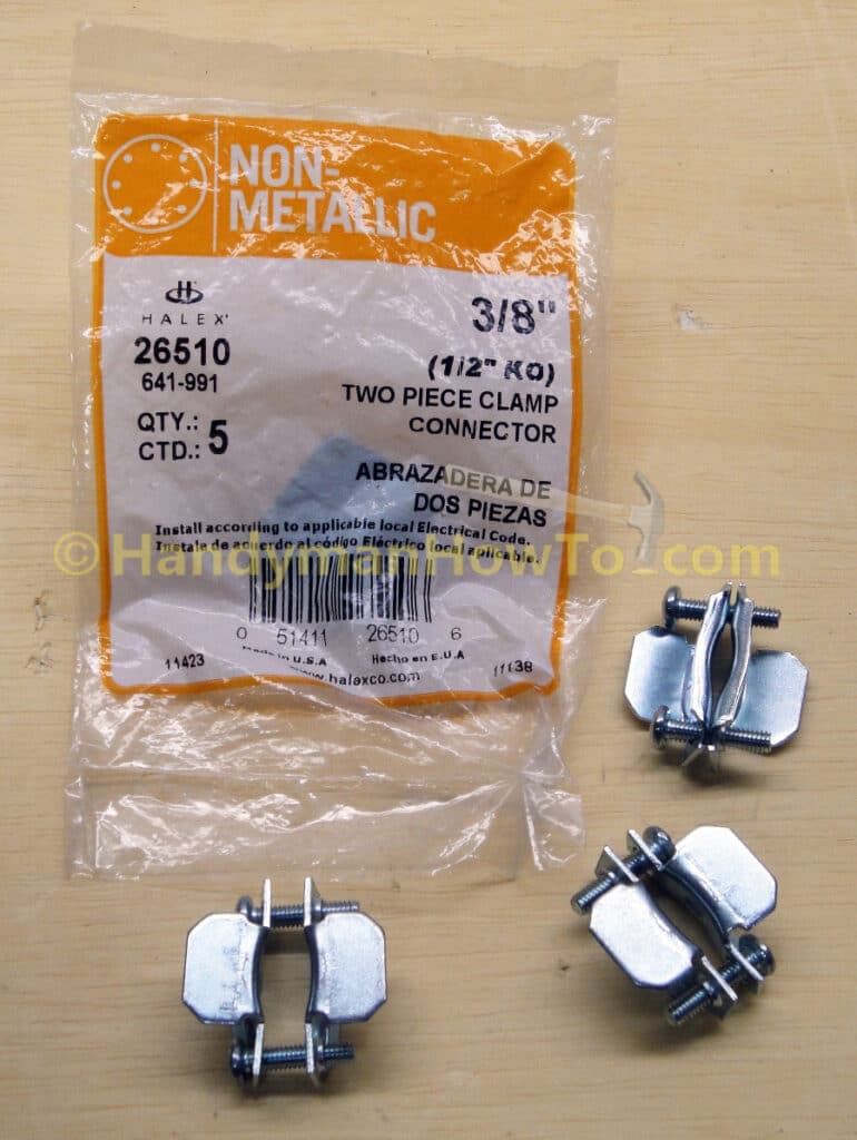
The NM cable clamps are installed by:
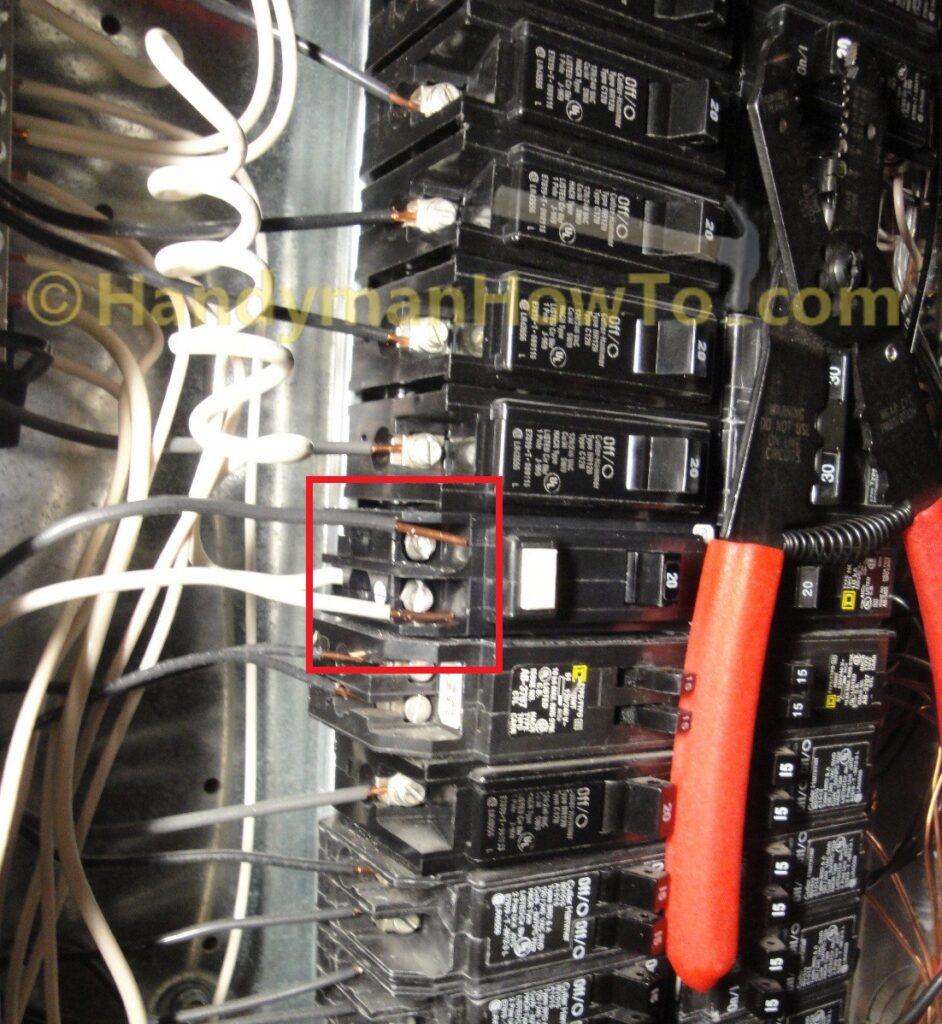
- Remove the two screws to separate the clamp halves.
- Insert the “wings” of the clamps through the bottom of the panel box on opposite sides of the cables.
- Reinsert the screws and tighten the clamp snug against the cables.
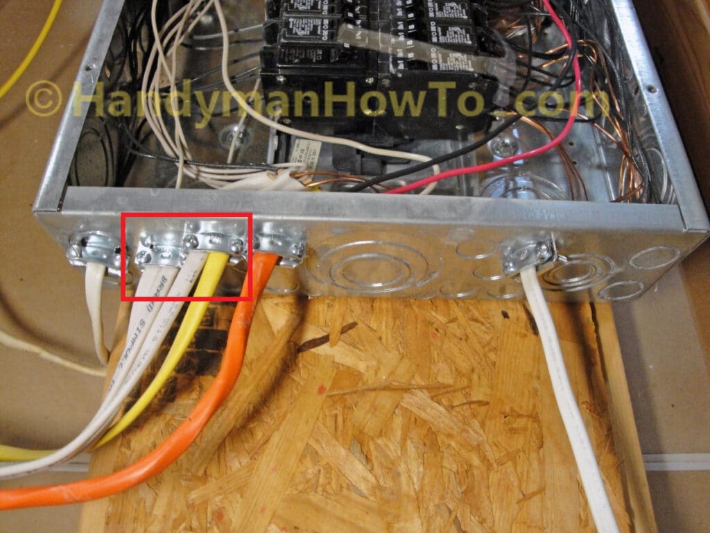
It is not necessary to disconnect the electrical cables. See the red box in this photo:
Branch Circuit Wiring: Ground Fault Circuit Breaker
The wiring steps for branch circuit connection to the Ground Fault Circuit Breaker (GFCB) are:
- Cut the NM-B 12/2 cable from the roll that was pulled to the kitchen sink such that there’s plenty of wire to connect to the GFCB, ground- and neutral bus bars in the panel.
The extra long cable will be trimmed to length later. - Remove the yellow outer insulation such that ~2 inches of yellow outer insulation extends past the NM cable clamp in the bottom of the panel box.
- Insert the cable through the NM cable clamp and the tighten the clamp snug on the cable.
- Fasten the ground wire at an unoccupied position in the ground bus bar. Tighten bus bar hold-down screw to 20 lb-in per the panel manufacturer’s instructions.
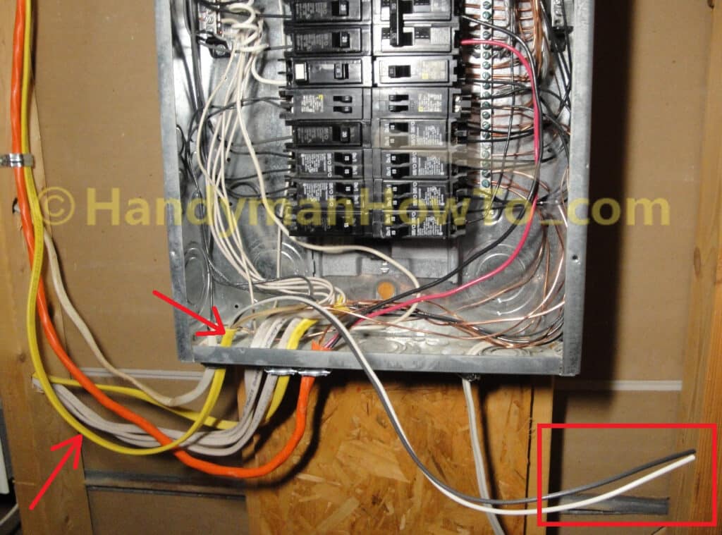
Take care to route your wires along the panel box bottom- and side gutters with wide gentle turns. The wires in the bottom of my panel aren’t routed or “dressed” as neatly as I would prefer because these were installed by the prior homeowner who lacked proper care and skills. The wiring in this other circuit breaker panel is a work of art.
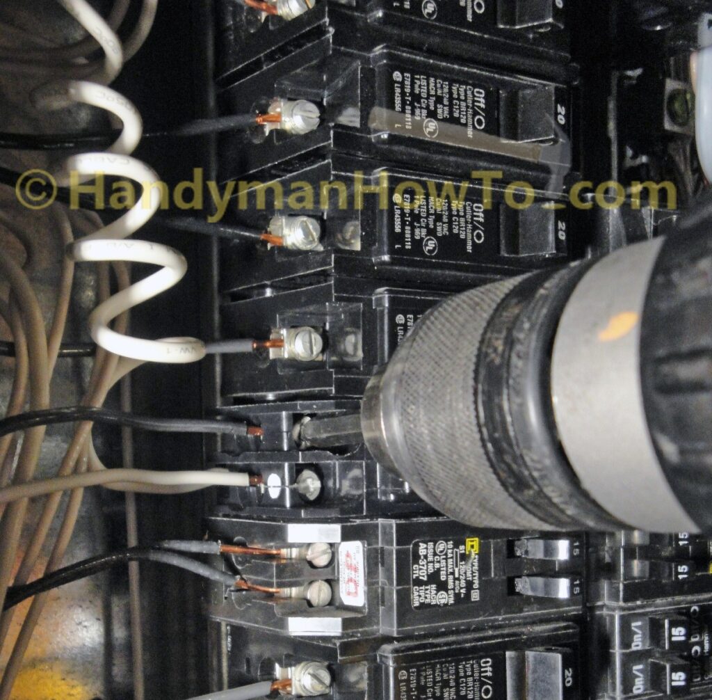
See the red arrows and red box highlighting the new cable:
The new black (hot) and white (neutral) branch circuit wires are routed in the gutter to the GFCB, cut to length and 5/8 inch of insulation stripped as shown:
The white (neutral) wire is attached to the neutral terminal marked by the white dot on the Eaton Cutler-Hammer Type BR 20 AMP (Part # GFCB120CS) ground fault circuit breaker. The black (hot) wire is secured to the other terminal. The terminals accept either a flat blade screw driver or a square drive bit; I’m using a square drive bit in my Dewalt cordless drill/driver. The terminal screws are tightened firmly – the breaker instructions didn’t specify a torque value in lb-in, so I went with 20 lb-in.
View of the finished wiring job. The GFCB is highlighted in the red box:
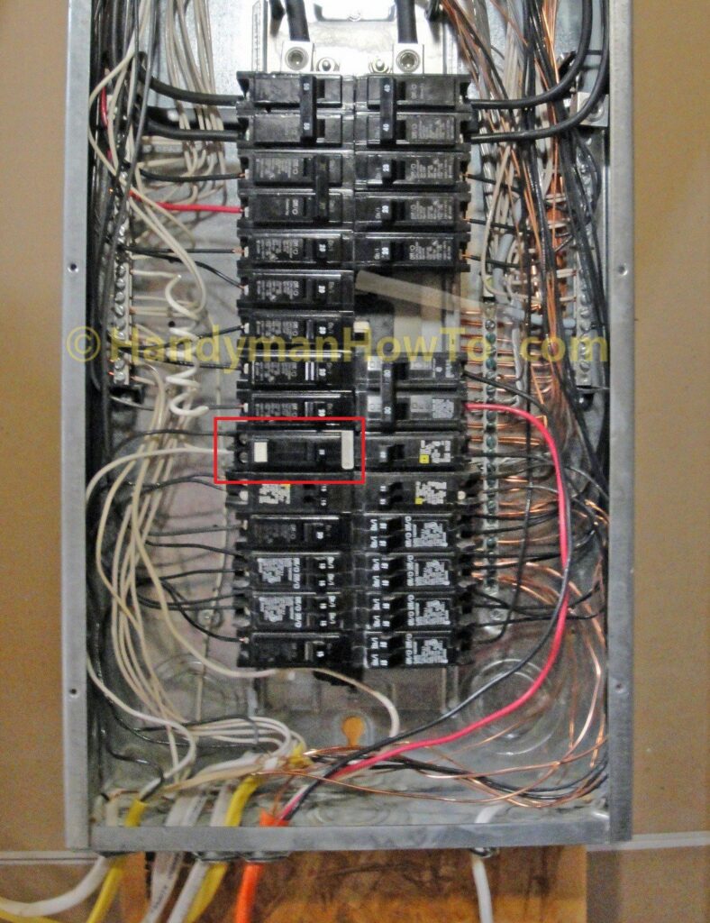
The 20 AMP branch circuit wiring for the under kitchen sink outlet is complete!
This project is concluded in How to Wire an Electrical Outlet Under the Kitchen Sink – Part 8.
Thanks for reading,
Bob Jackson