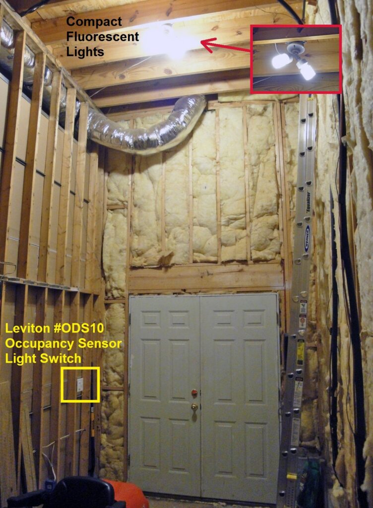
This tutorial explains how to install a Leviton ODS10 Occupancy Sensor Wall Switch that is compatible with any light, including Compact Fluorescent Lamps (CFL) and incandescent light bulbs.
Lighting Automation
The back room in my basement storage area has a light switch at the far side next to the exterior doors. The only way to reach the light switch was to stumble in the dark while holding my arms out zombie-style to avoid running into something. My first improvement was to replace the wall switch with one that had an illuminated handle that glowed when the light switch was Off, so I could at least have a point of reference. This helped, but was unsatisfactory because I would still trip over the lawn mower and other stuff.
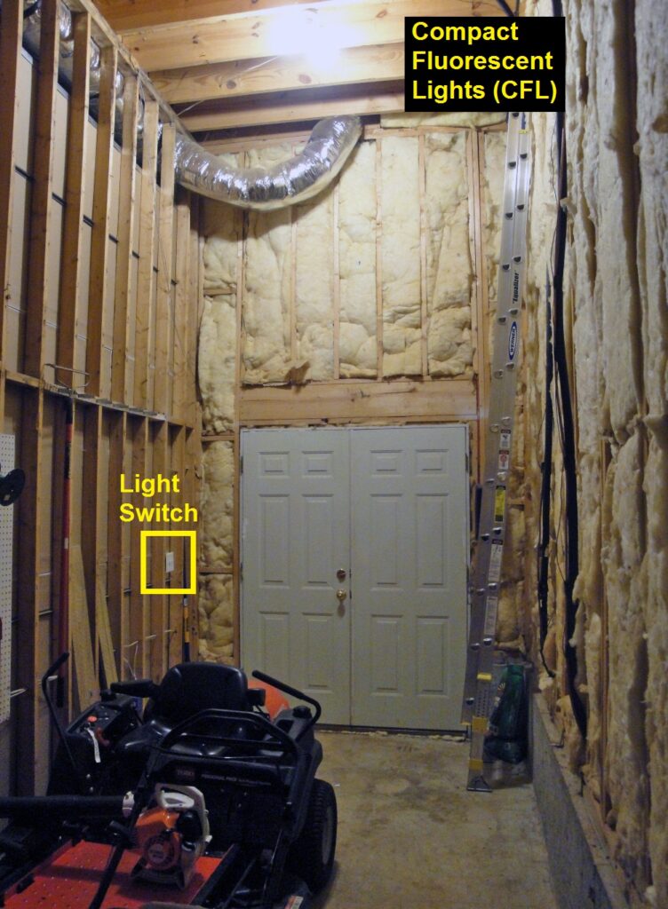
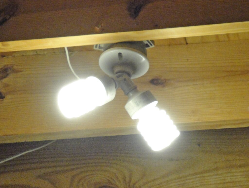
What I needed was an occupancy sensor light switch to sense motion in the room and automatically turn On/Off the overhead CFL lights:
CFL Compatible Occupancy Sensor Light Switch
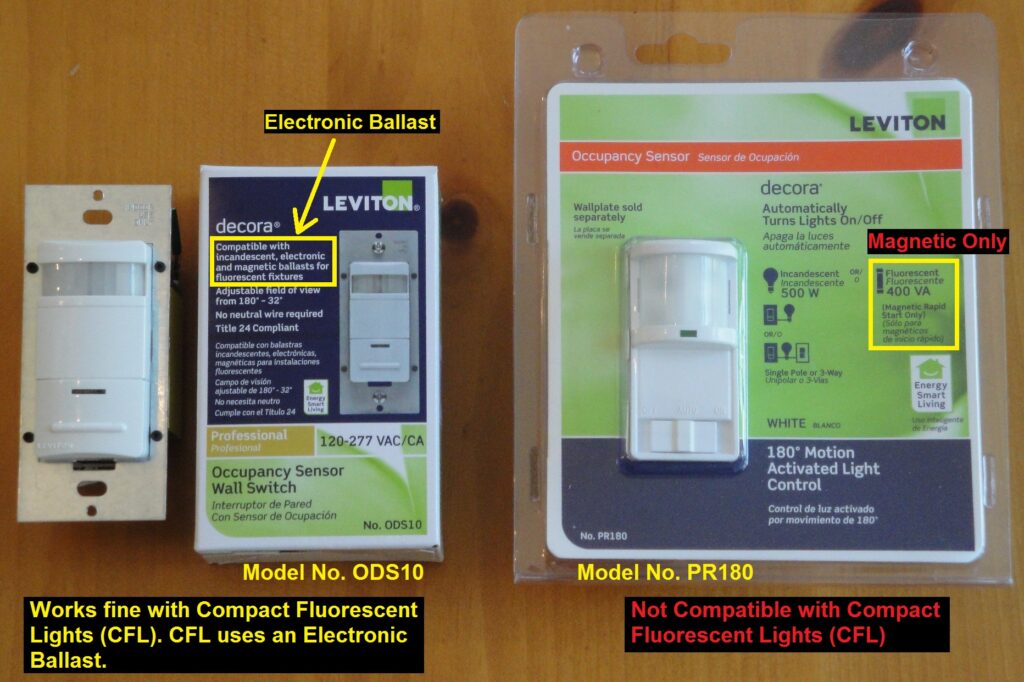
I purchased a Leviton Occupancy Sensor Light Switch Model PR180 at the local home improvement store, only to learn upon reading the product specifications in detail that it won’t work with Compact Florescent Lamps (CFL). The problem is the PR180 isn’t compatible with the “electronic ballast” in a CFL. The electronic ballast is the miniaturized circuitry in the base of a CFL bulb that provides the high frequency voltage to power the lamp. The PR180 will operate a traditional incandescent light bulb or older style fluorescent lights that use a magnetic ballast. Magnetic ballasts are characterized by the bulky coil windings.
After further research, I found the Leviton Occupancy Sensor Wall Switch model ODS10 is compatible with all types of lights, including Compact Fluorescent Lamps (CFL).
Leviton ODS10 Occupancy Sensor Wall Switch Review
The Leviton ODS10 has several nice features:
- Wide 180 degree sensing zone.
- Passive infrared (PIR) sensing technology.
This means it senses body heat to detect motion. - Red LED indicator flashes when motion is sensed.
- Adjustable Off time delay from 10 to 30 minutes.
- Push-button manual On and Auto-Off mode for energy savings.
- Presentation mode: If the lights are On, pressing the push-button with turn
the lights off and ignore motion events until the time delay expires. - Adjustable ambient light level to prevent the light from turning on
when there’s natural sufficient light. Or the you can adjust the switch
to turn on the lights unconditionally, even in full daylight. - Adjustable detection range.
- Two independent adjustable blinders such that motion in adjacent areas
doesn’t turn on the light. For example, so that people walking in the
hallway don’t cause the light in the room to turn On. - 5 year warranty.
The ODS10 is available in several colors (white, ivory, light almond and gray) to match your home decor.
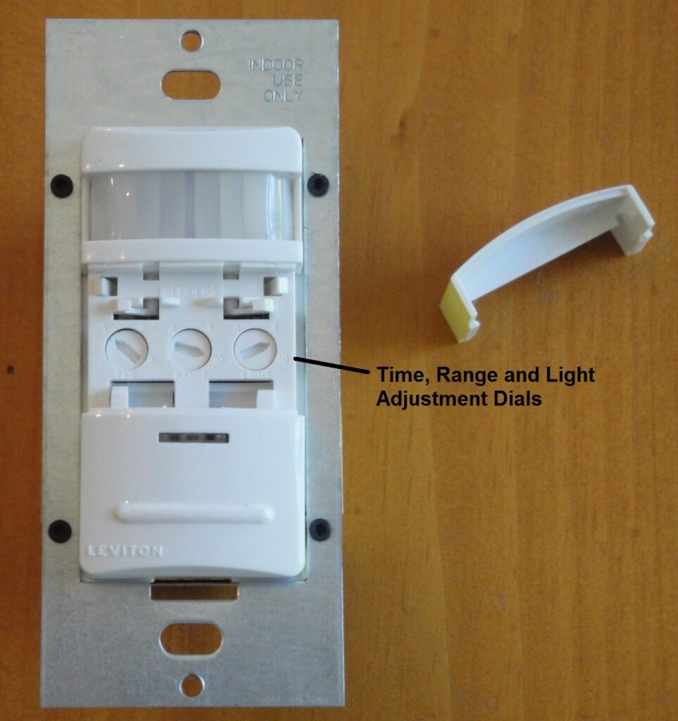
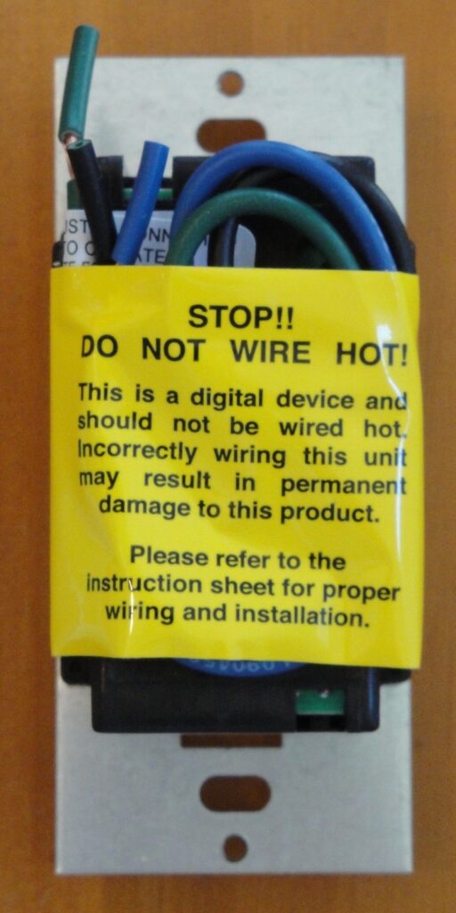
The Leviton ODS10 timer, range and light adjustment dials are located behind a snap-on cover:
Rear view of the ODS10 wall switch. Obviously, electrical wiring should never be performed on a live circuit for personal safety; always turn off the electricity before installing.
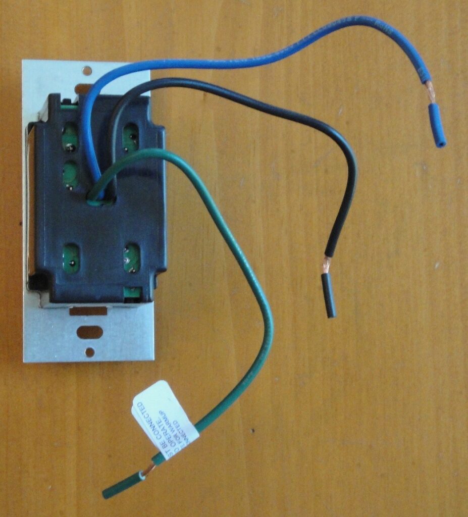
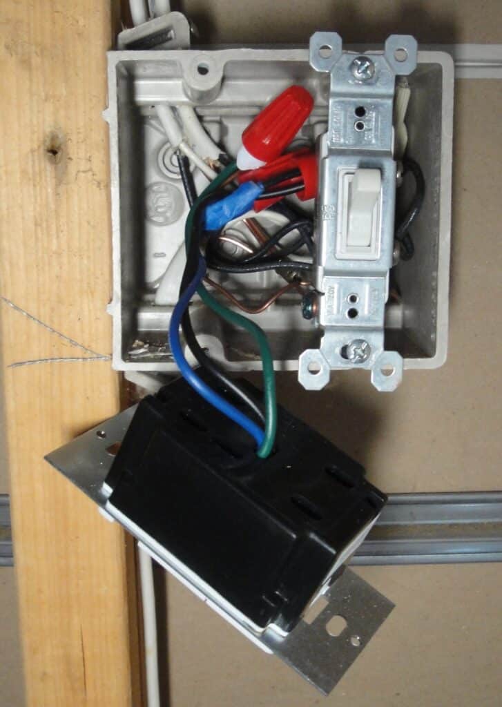
The Leviton ODS10 switch is a bit bulky and requires an electrical switch box at least 2-3/4 inches deep:
The Leviton ODS10 has three wires:
- Black – (hot) line side wire.
- Blue – load side wire.
- Green – ground wire.
Leviton ODS10 Occupancy Sensor Wall Switch Installation
These installation steps show how to install the ODS10 in a single control light switch application. See the Leviton ODS10 installation instructions if you’re replacing a 3-way light switch controlled from two locations – this will require two (2) ODS10 wall switches.
If you’re uncomfortable with electrical wiring or lack the proper tools, care and attention, please hire a licensed electrician to install the occupancy sensor switch.
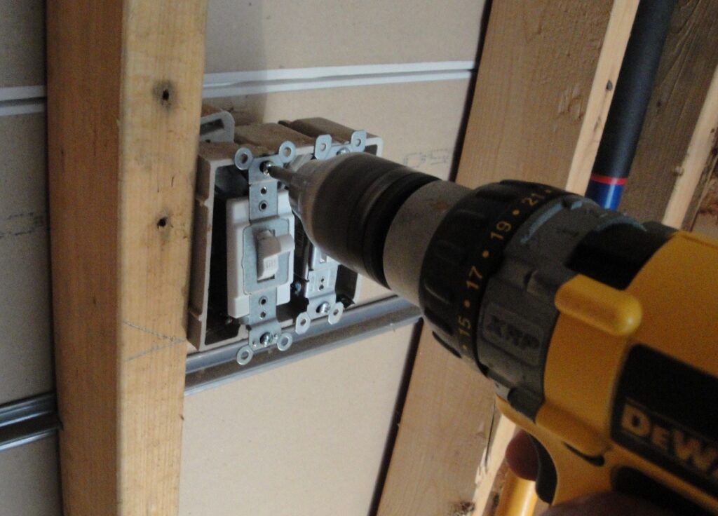
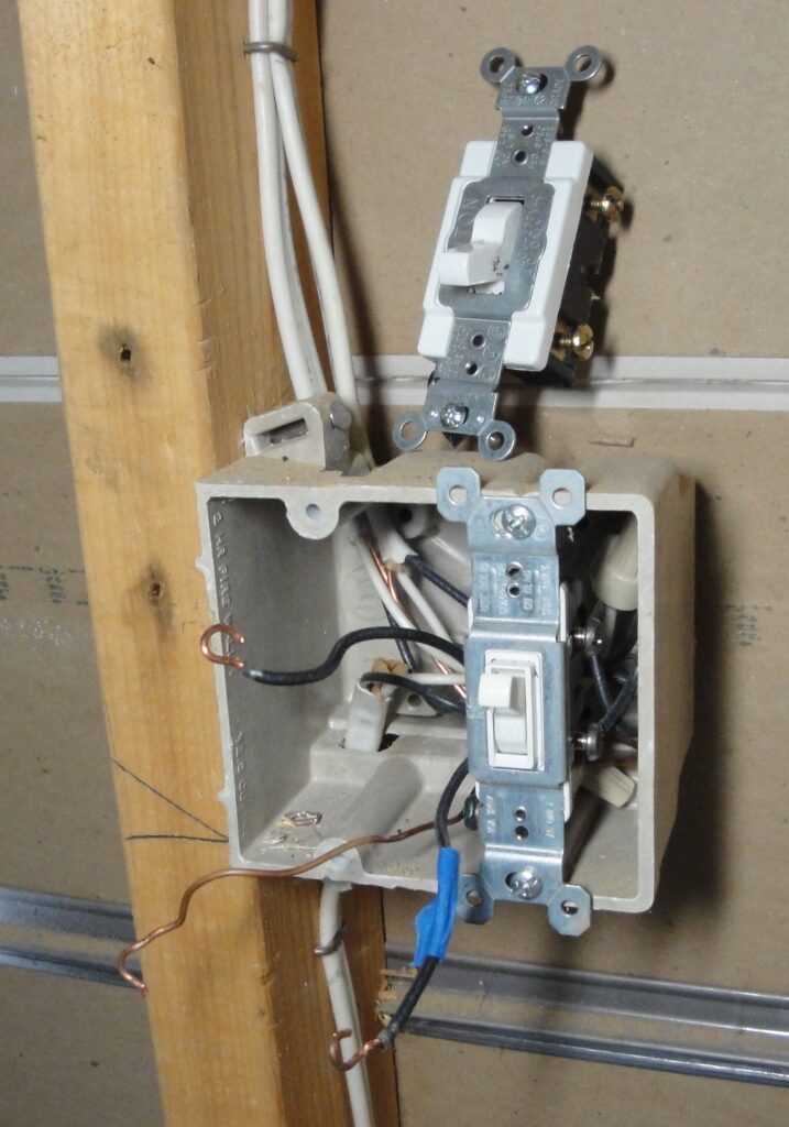
I began by shutting off the electricity to the basement lights at the main circuit breaker panel, then removing the old light switch mounting screws to release the switch from the wall box. There are two screws – top and bottom. I’m working by the light of a battery power lantern.
Identify the Line Side Electrical Wire
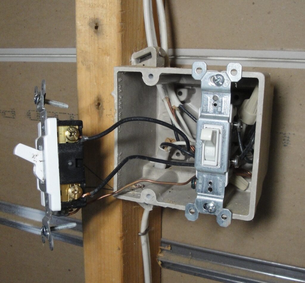
With the circuit breaker Off and having removed the toggle switch mounting screws, I gently pulled the switch out of the electrical box unfolding the wires (see below).
I installed this Leviton illuminated light switch and know for a fact the bottom black wire is the “line side” or “hot” wire that receives power from the circuit breaker panel.
For a single light switch control, the lower black wire is the line side if the switch is Off when the handle is in the down position. However, in a new situation you can’t trust the electrician (or maybe the previous homeowner) wired the switch correctly, so it’s best to verify which black wire is the hot or line side circuit connection.
Be extra careful in these next steps; keep the family, kids, dogs, cats and all distractions away! Remove all necklaces, watches and bracelets.
To identify the line side (hot) wire:
- Make sure nothing is touching the electrical switch or wires.
- Turn on the power at the electrical circuit break panel.
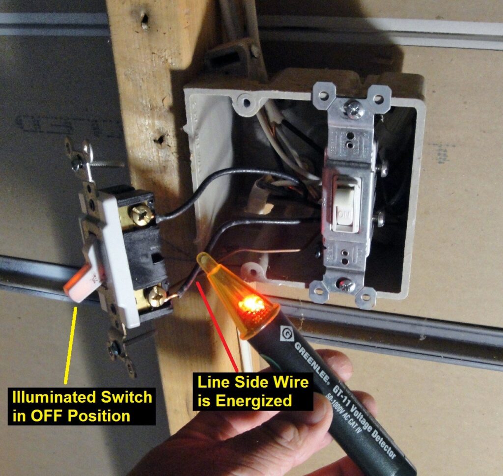
- Notice the illuminated switch is now glowing in the Off position.
This immediately tells me the lower black wire is the line side, otherwise the switch handle wouldn’t illuminate. - Verify the lower black wire is energized with a non-contact voltage detector.
The detector will flash and beep to indicate the wire is energized (live).
Take care not to touch the exposed side screws or bare wires to avoid an electrical shock!
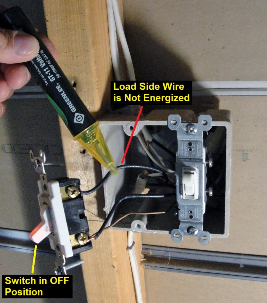
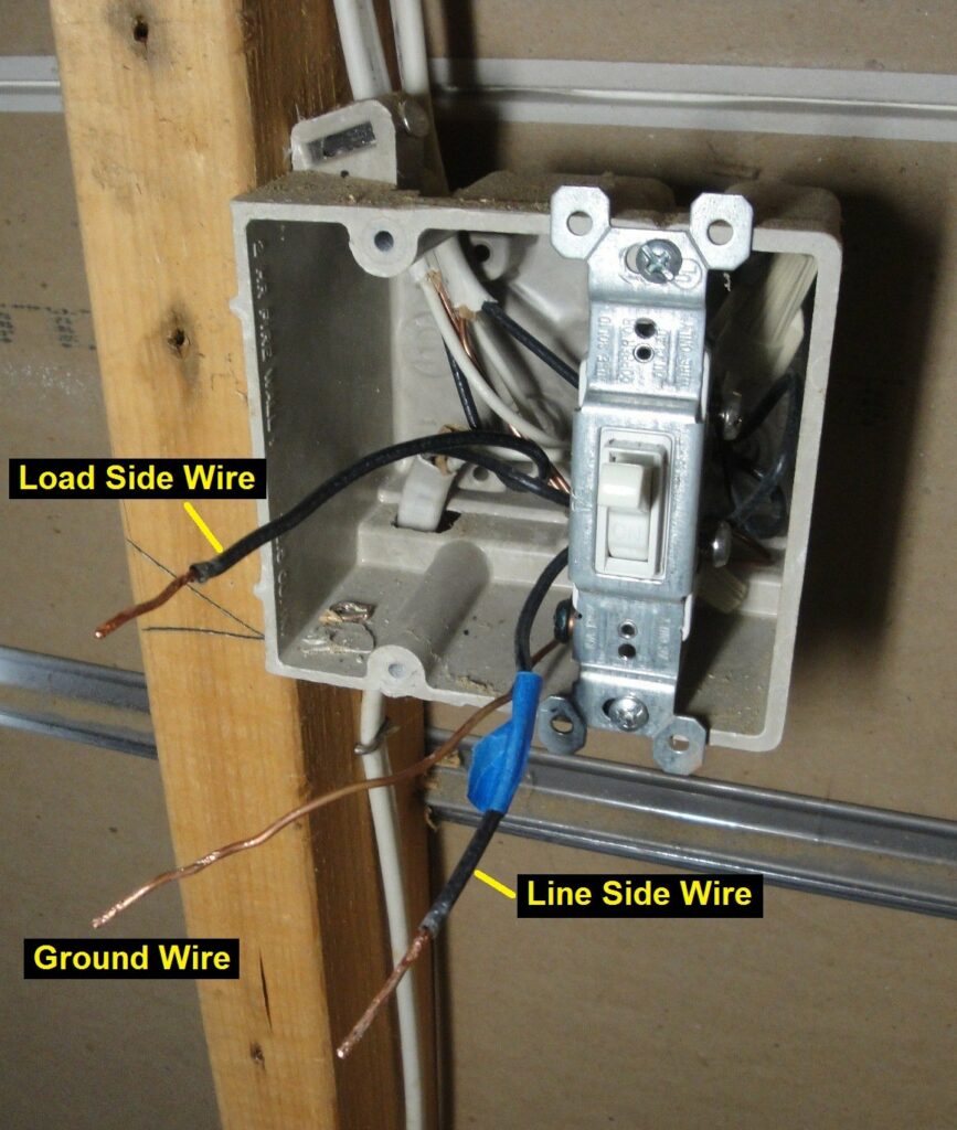
A secondary check against faulty wiring is to verify the upper black wire is the load side with no power when the toggle switch is in the Off position. The non-contact voltage detector is silent indicating the wire is not energized (no electricity):
Moving the light switch to the On position completes the circuit and powers the load side black wire, turning on the lights. The load side wire is now energized with electricity as indicated by the flashing and beeping voltage detector:
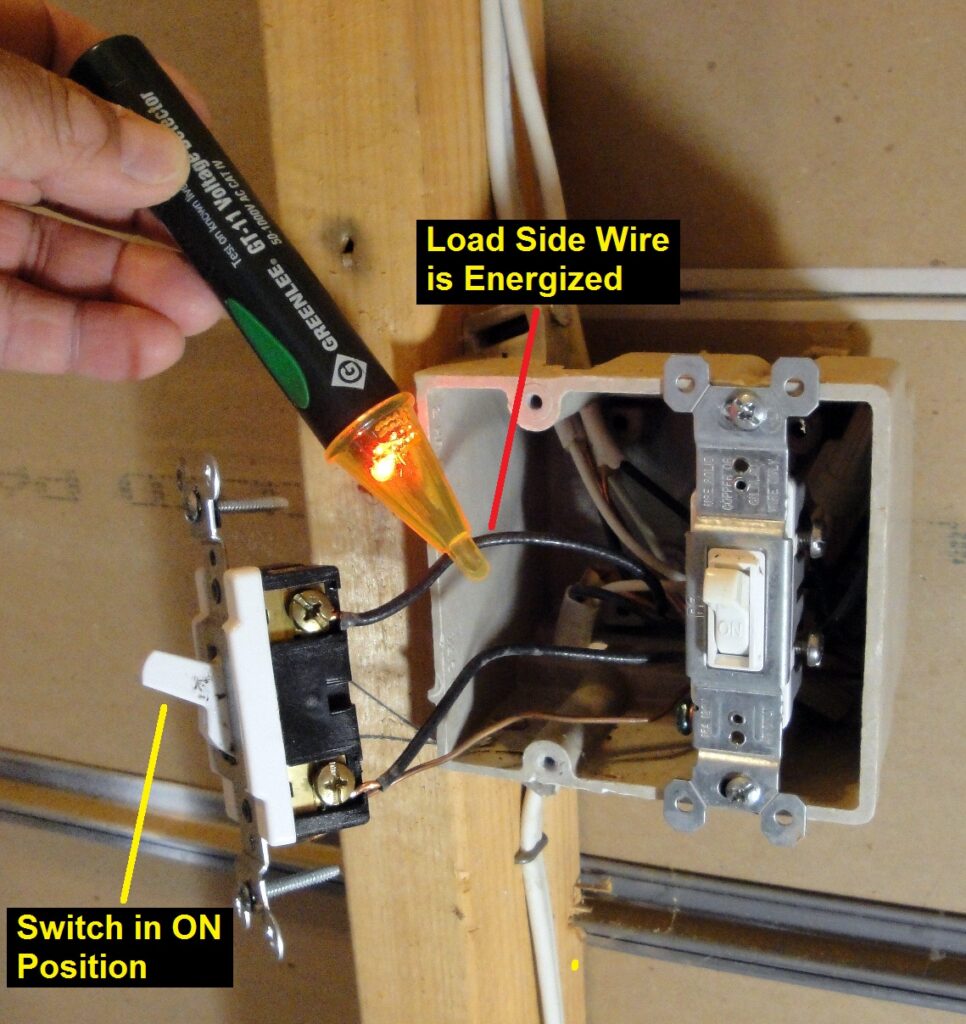
The lower black wire is now confirmed as being the line side (hot) wire and the upper black wire as the load side wire going to the lights.
Tag the Line Side Hot Wire
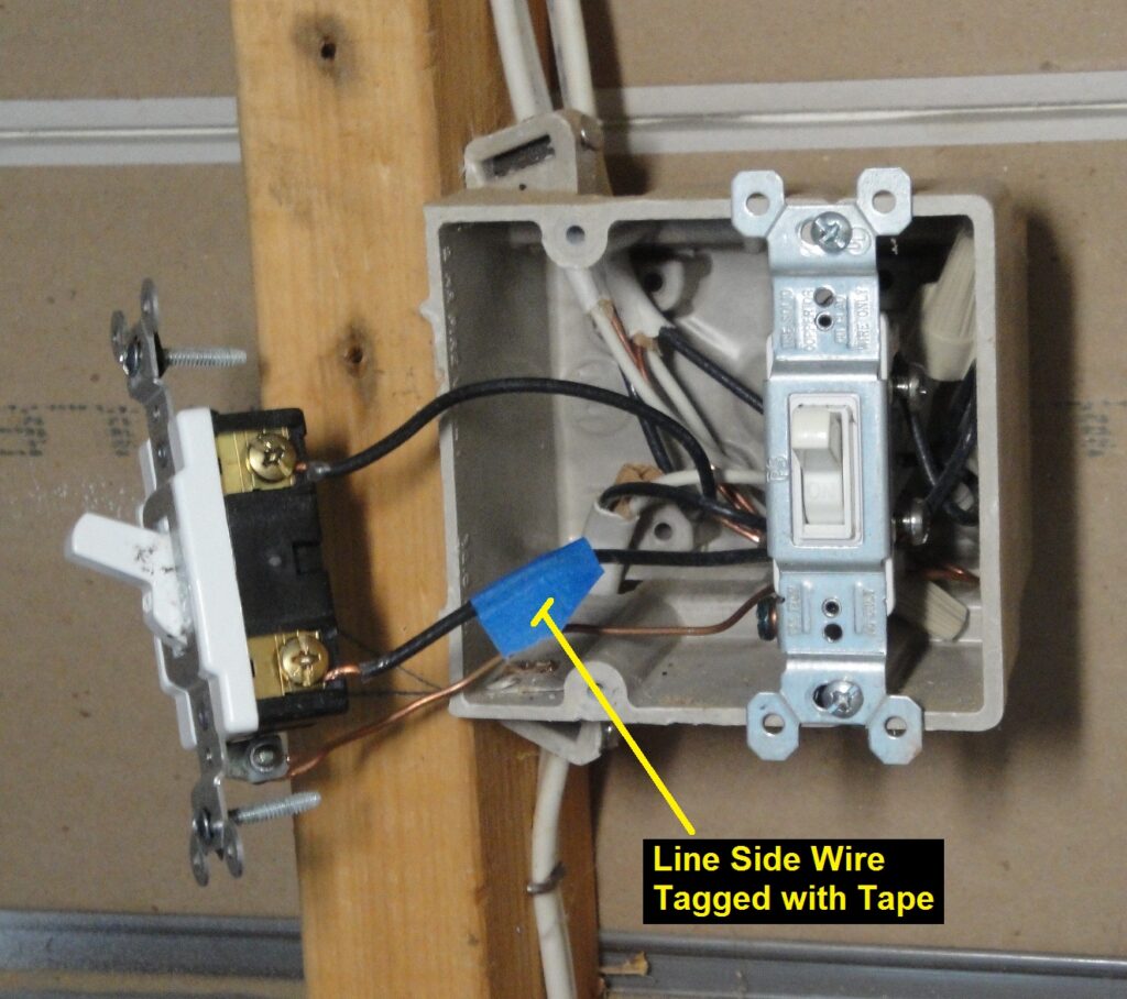
Turn off the electricity at the circuit breaker panel before proceeding!
After shutting off the electricity to the light switch and double checking the circuit is dead with the voltage detector, I tagged the line side (hot) black wire with a small piece of blue tape so I won’t mix up the wires when I remove the light switch.
As Sgt. Esterhaus says in Hill Street Blues: “Let’s be careful out there!”
Remove the Light Switch
With the circuit breaker Off to disconnect the electricity from the light circuit, the side screw terminals are loosened to remove the two black wires. The ground screw is loosened to disconnect the bare copper ground wire from the toggle switch. You may need to pry open the looped wire ends with the tip of screwdriver to slip the wires off the screw shank.
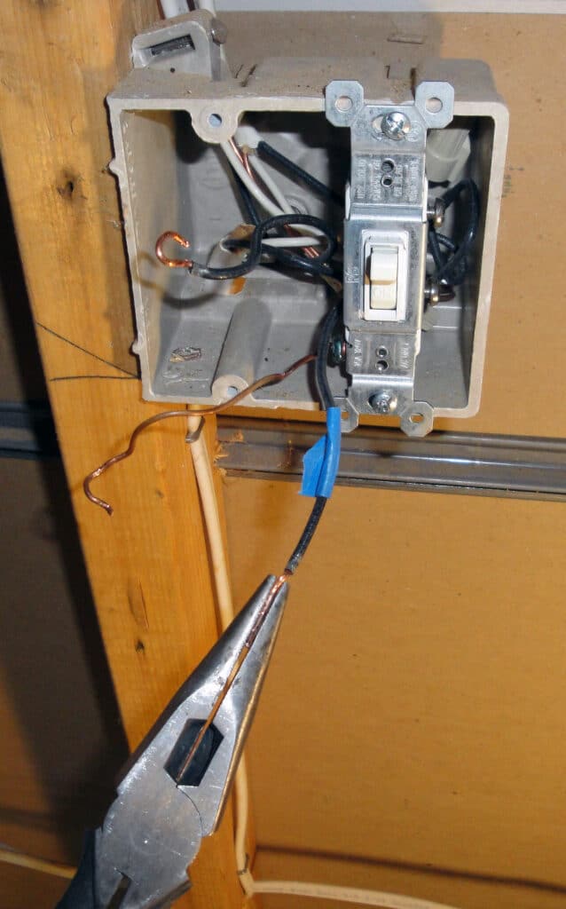
Dress the Light Switch Electrical Box Wires
The Leviton ODS10 Occupancy Sensor Wall Switch will be attached to the electrical box wires with twist on wire nuts. The light circuit wires in the electrical box must be straightened and trimmed, or dressed for the Leviton ODS10 switch installation. Gently uncurl the looped wire ends with needle nose pliers so the wire is mostly straight, then perform a final straightening with the needle nose pliers held lengthwise as shown to flatten the wire in the “up/down” direction. Rotate the pliers 90 degrees and squeeze again to straighten the wire end in the “left/right” direction.
The three electrical wire ends are now (nearly) straight, suitable for wire nutting:
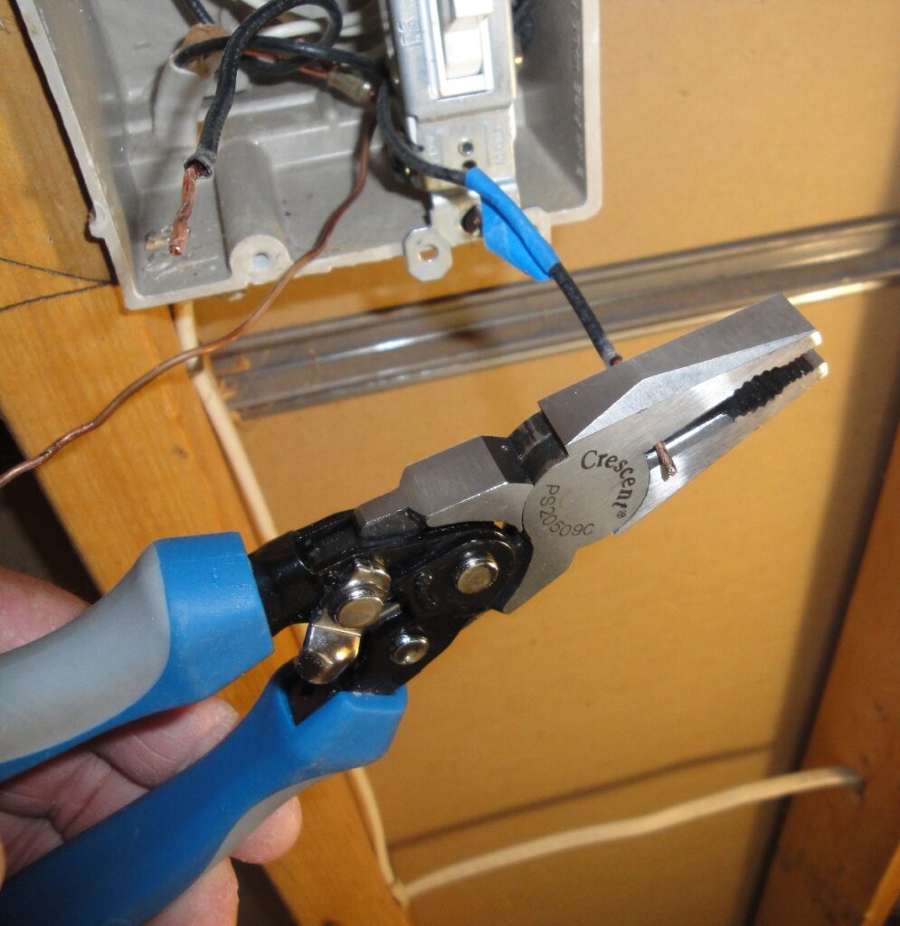
The exposed bare copper ends of the black wires are too long for wire nutting. I cut the exposed ends to 5/8 inches long with electrician’s pliers such that the bare copper portion will be fully covered by the wire nuts. Note that there is no need to shorten the bare ground wire.
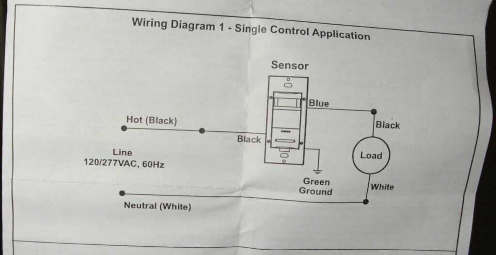
Leviton ODS10 Wiring Diagram
My lighting application corresponds to the “Single Control Application” wiring diagram in the Leviton ODS10 instructions. The wiring is straightforward:
- Line side (Hot) black wire (tagged with a piece of blue tape) is connected to the black wire on the Leviton ODS10.
- Load side black wire is connected to the blue wire on the ODS10.
- Bare ground wire is connected to the green wire on the OSD10.
The “load” in the wiring diagram are the compact fluorescent lights (CFL).
The ODS10 requires the ground wire connection to operate.
Leviton ODS10 Occupancy Sensor Wiring
Wire nuts are not included with the Leviton ODS10, so you must provide these. I’m using red twist on wire nuts rated for minimum of two (2) #14 gauge and a maximum of four (4) # 12 gauge wires. My electrical box house wiring is NM-B 14/2 (i.e. 14 gauge, 2 conductors plus ground) and the ODS10 has 14 gauge stranded copper wires.
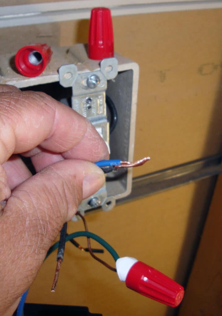
To wire the ground connection:
- Pull the pre-stripped insulation off the end of the end of the ODS10 green ground wire.
- Hold the bare copper ground wire from the wall box against the ODS10 green ground wire.
- Pre-twist the two wires clockwise with your fingers.
- Make sure the wire ends are even.
- Twist on the red wire nut in a clockwise direction (righty-tighty) until tight.
No need to over do it, the wire nut will cinch down tight when the wires bottom-out.
Follow the same procedure to wire nut together the ODS10 blue wire with the load-side black wire. Recall the load side black wire WAS NOT tagged with the blue tape.
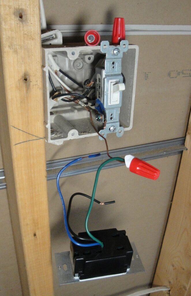
The Leviton ODS10 black wire is nutted to the line side (hot) black wire tagged with the piece of blue tape as seen on the left side of this photo:
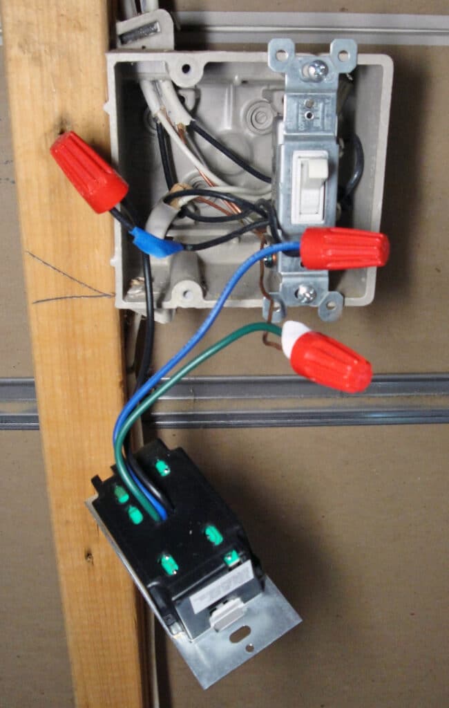
Mount the Leviton ODS10 to the Wall Box
Gently fold the wires into the electrical wall box with easy bends, taking care not to kink or pinch the wires:
Mount the ODS10 to the wall box using the included two long screws:
Leviton ODS10: Time, Range & Light Adjustment Dials
I removed the adjustment dial cover by prying it off with the tip of a screw driver. Next, I turned On the electricity by switching On the circuit breaker. I decided it was better to test the ODS10 before installing the wallplate cover just in case there were a wiring problem.
The timer, range and light sensitivity dials are left-to-right respectively:
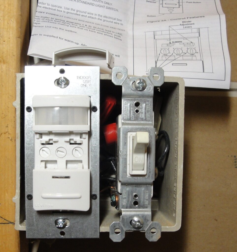
I turned the timer dial the left slash mark to select the 30 second time-out for testing, then adjusted the range sensitivity to maximum and the light level dial to a fairly dark setting. I tested the occupancy sensor by walking into the room and was very happy when the lights came on as soon as I was within sight of the ODS10. I set the timer to a 10 minute time-out to save electricity; the lights will stay on so long as motion is sensed, resetting the 10 minute time-out so being caught in the dark is not a concern. The push button On/Off manual override also worked fine.
Unbreakable Nylon Wall Plate
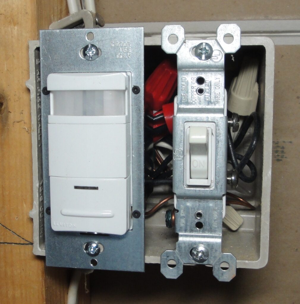
Since this is a workshop area, I purchased a Leviton unbreakable nylon wallplate with matching rectangular and toggle switch cutouts for the new OSD10.
The nylon face plate looks very nice. The Leviton ODS10 has a red LED that flashes when it senses motion so you know it’s working.
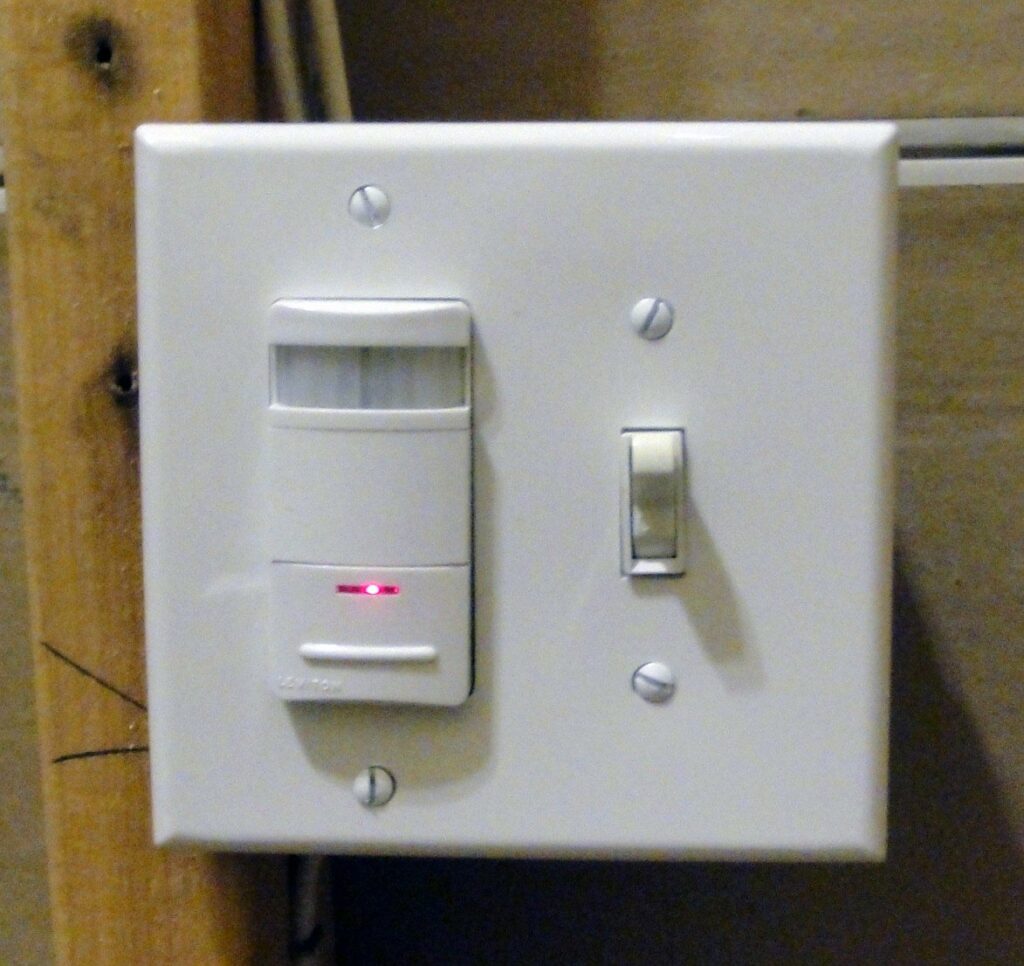
Leviton ODS10 Occupancy Sensor with Compact Fluorescent Lights
The new Leviton ODS10 occupancy sensor works great! The lights turn on automatically when I’m at the threshold to the room. The sensor even turns the lights on when the exterior door is opened as I enter from the outside, detecting the motion of the door. And I never have to bother with turning off the lights. The occupancy sensor is a really nice convenience! I installed two more of the ODS10’s in the bathrooms.
Thanks for reading,
Bob Jackson