This project shows how to wire an attic electrical outlet and light. The old switch and light are removed, then a new electrical outlet is wired for a fluorescent shop light to brighten up the attic.
How to Wire an Attic Electrical Outlet and Light
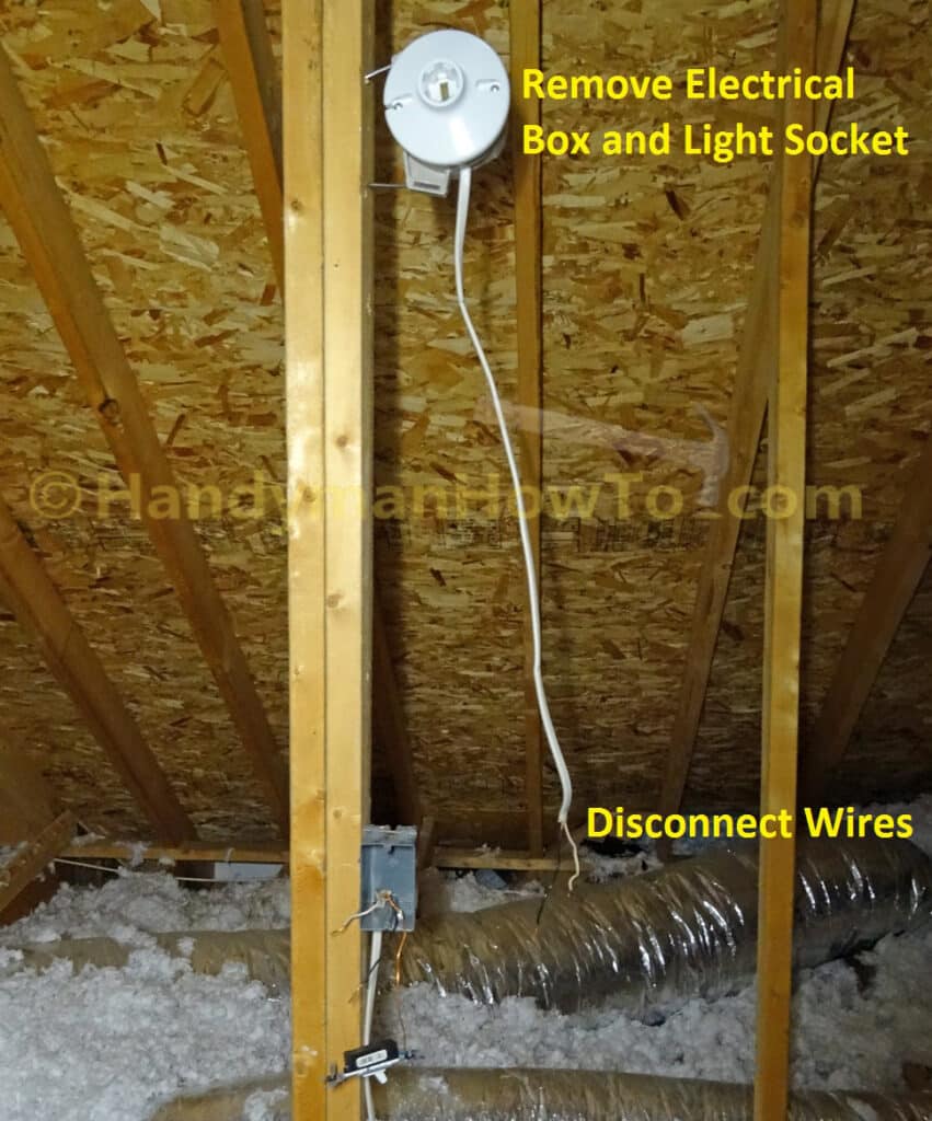
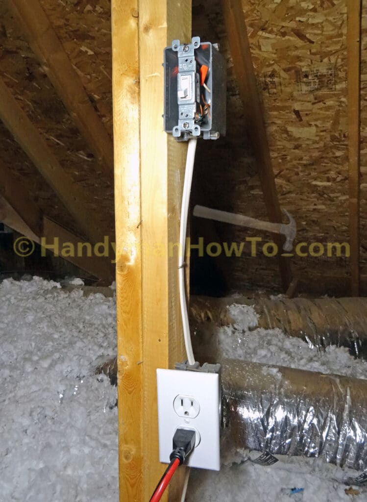
I plan to replace the flexible air ducts in the attic with round metal ducts for better efficiency and didn’t want to be working in a dark attic illuminated by a single 100 watt light bulb. The home builder installed the electrical outlet, light switch and light socket by the folding attic stairway (I’ve removed the switch box faceplate here):
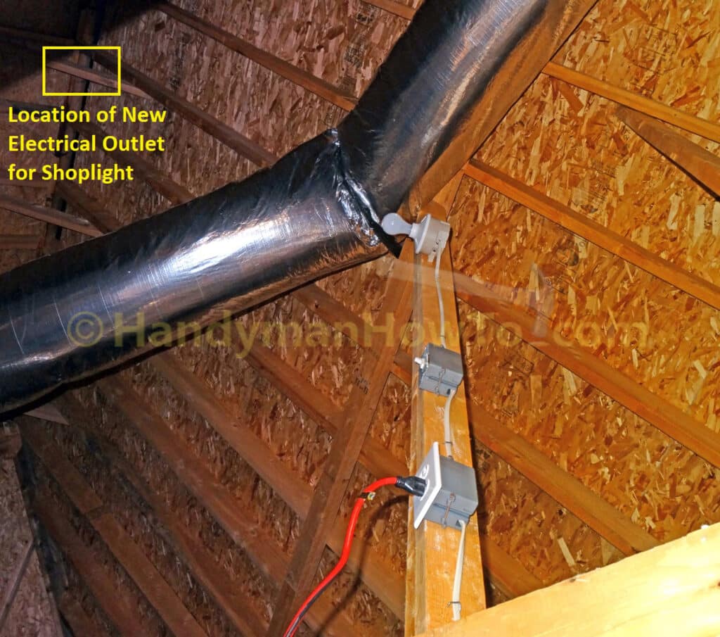
 Attic Fluorescent Shop Light and Electrical Outlet Wiring
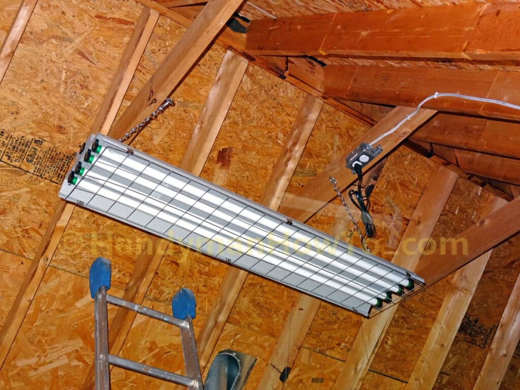
The attic shop light is suspended by chains from the rafter collar ties and plugs into the switch-controlled electrical outlet connected to the light switch next to the attic stairs. This photo only looks bright because of the camera flash:
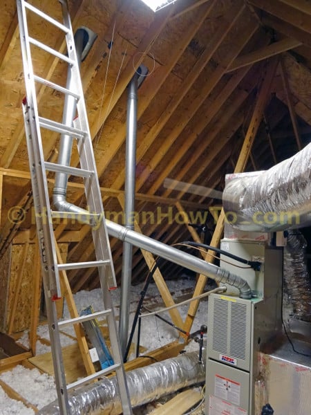
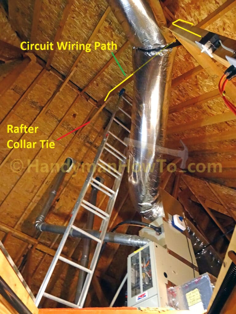
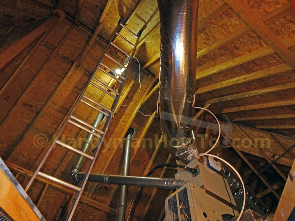
Note the 16 foot extension ladder needed to reach the rafter collar tie due to the high steep roof:
Attic Light and Outlet Wiring Diagram
The wiring diagram for the new attic light, switch-controlled duplex outlet and toggle switch explains how the new circuits are wired:
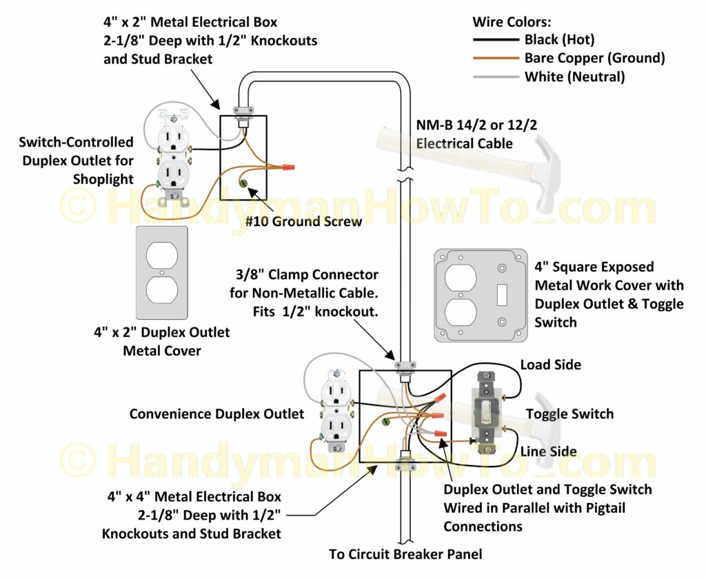
Due the way the home builder wired the original duplex outlet and light switch, I had to remove those items and wire in a new 4 inch square electrical box, duplex outlet and toggle switch by the attic stairway.
Electrical Safety
Shutoff the electricity at the circuit breaker panel before working on the wiring, then verify the power is off with a voltage detector to avoid electric shock, injury and/or death. If you’re uncomfortable working with electricity hire a licensed electrician.
Electrical Permit
An electrical building permit is required when wiring new circuits because this constitutes more than a minor repair. You’ll also want an electrical permit if having work done by a licensed electrician to ensure the work was done properly. The building permit fee in my county is $50 and a minor cost compared to the dangers of improper wiring.
Disconnect the Old Attic Light
The old electrical box wiring is disconnected from the toggle switch box. The light electrical box is fastened to the 2×4 framing with two nails, which was easily pried off with a long screw driver.
Ground Wires Don’t Meet the Minimum Conductor Length
My plan was to extend the wiring for the new switch-controlled electrical outlet from the existing light switch box. However, instead of leaving the minimum 6 inches for the ground wires which must also extend at least 3 inches outside the box, the electrician:
- twisted the main ground wires together
- cut the ground wires off inside the box
- used a crimp sleeve connector to make the light switch ground wire connection
While crimping and cutting off ground wires may be common practice by some electricians, I don’t like it because it’s makes rewiring very difficult and violates National Electrical Code (NEC) article 300.14 which states (bold emphasis added):
NEC 300.14 The minimum length of conductors, including grounding conductors, at all boxes shall be 6″. At least 3″, of every conductor, shall extend outside the box.
Check with your local building department or authority having jurisdiction (AHJ) if in doubt.
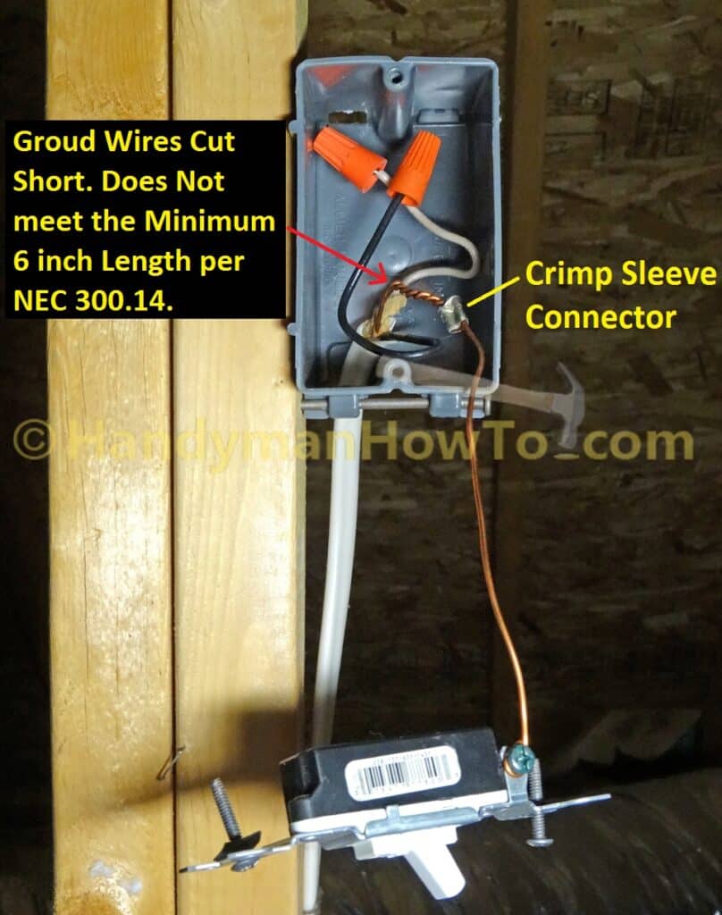
Because there’s no slack in the NM-B 14/2 cable to pull extra wire into the switch box, I’ll have to make a trip to the home improvement store to buy a 4-inch square junction box to replace the entire setup.
For now, I’ve temporarily capped the hot (black) and neutral (white) wires with wire nuts (see above photo) and remounted the disconnected light switch so I can use the electrical outlet by the attic stairway to power my trouble light. Capping the wires with wire nuts is necessary to prevent an electrical short and shock hazard when I turn on the electricity at the circuit breaker panel.
Attic Electrical Outlet Wiring Tools & Materials
I used the following tools and materials to wire the new electrical outlet for the attic light:
A. Gardner Bender Cable Boss Staple Gun
C. Voltage and receptacle testers
D. Screw drivers and utility knife
E. Linesman and needle nose pliers
F. DeWALT cordless drill/driver
I. Leviton heavy duty duplex receptacle
J. 2in x 4in steel electrical box with stud mount bracket and steel cover plate
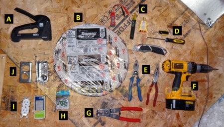
Sorry for the somewhat blurry photo above, it was dark in the attic and camera didn’t quite focus while using the flash bulb.
Attic Electrical Outlet Wiring Path
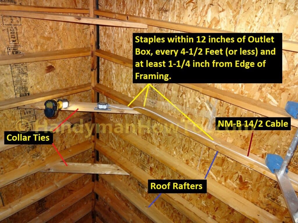
The electrical outlet will be mounted to the rafter collar tie following the wiring path in yellow along the 2×4 framing and roof rafter. I was a bit surprised just how high the attic is with the steep roof. I initially hauled up my 6 foot step ladder but it was way too short, instead I had to get the 16 foot extension ladder, taking care to mount a section of 5/8″ plywood on the joists with wood screws to stand the ladder on.
Attic Electrical Outlet Wiring
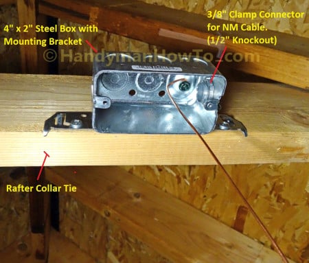
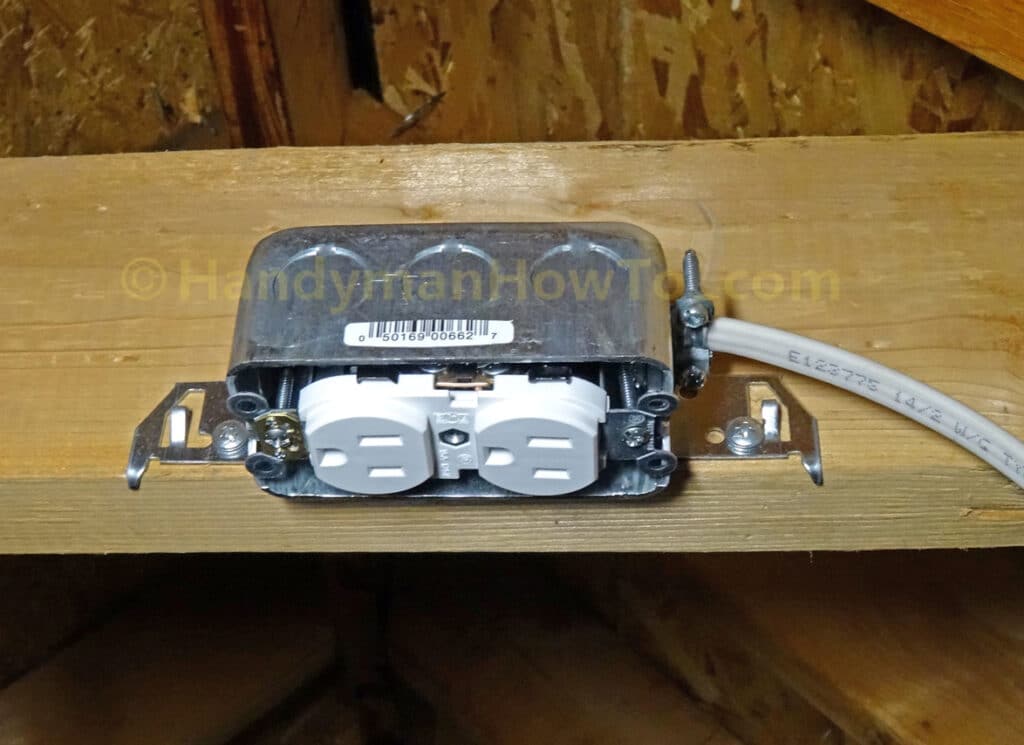
A 4in x 2in steel outlet box is mounted to the rafter collar tie with two pan-head wood screws. This particular drawn steel box is 1-7/8 inches deep, but I prefer the 2-1/8″ deep steel boxes for the extra room and would have used it, however the local home improvement store was sold out.
Next, the 1/2 inch knockout is removed by tapping it open with a screw driver and breaking the knockout plug off with pliers. A 3/8″ non-metallic cable clamp connector is inserted and the locknut screwed on tight.
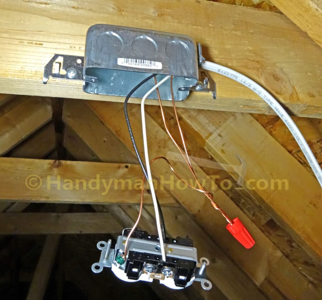
Steel outlet boxes must be grounded. A #10 green ground screw is fitted to the threaded hole for this purpose, an ~8 inch length of 14 gauge ground wire pigtail is wrapped clockwise around the screw, then the ground screw is securely tightened. The ground wire pigtail is obtained by cutting a section of NM-B 14/2 cable from the roll and pulling out the ground wire.
Stripping NM-B Cable
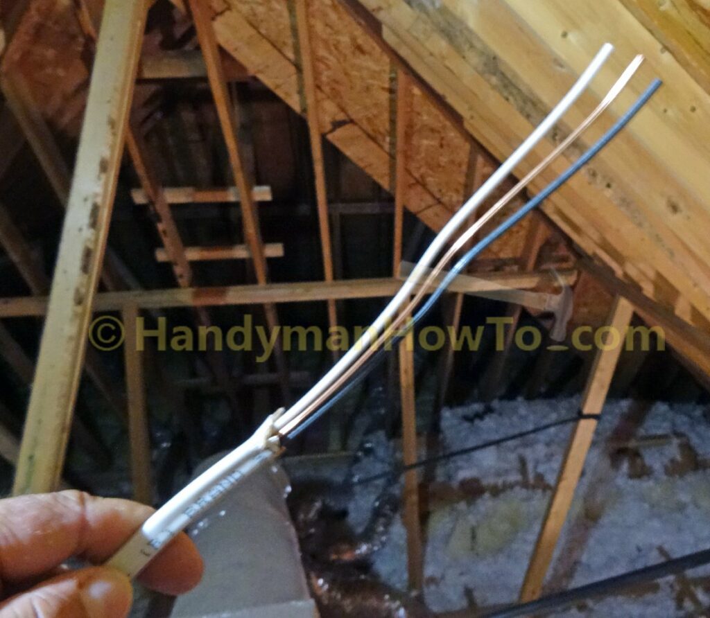
Prepare the NM-B 14/2 cable for wiring the attic outlet by making a shallow 1/2 inch long cut with the utility knife in the center outer insulation jacket at the end of the cable, then pull the insulation jacket down the wires to peel it like a banana to expose about 8 inches of wires. This method avoids damaging the hot and neutral wire insulation with the knife.
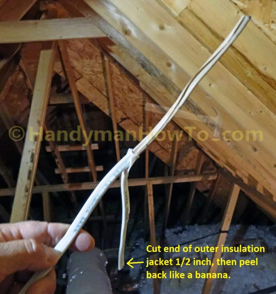
Cut off the outer insulation jacket and remove the inner paper wrap:
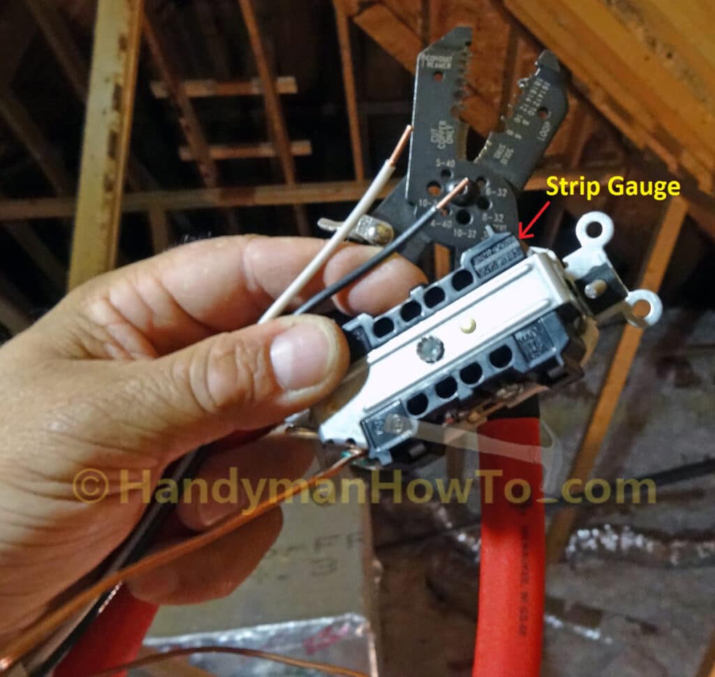
Use the strip gauge on back of the outlet to strip the hot (black) and neutral (white) wire insulation to the correct length with the wire strippers, using the 14 gauge solid notch printed on the jaws. In this photo, I’ve also connected a generous length of bare copper ground wire to the green ground screw on the outlet (lower left side).
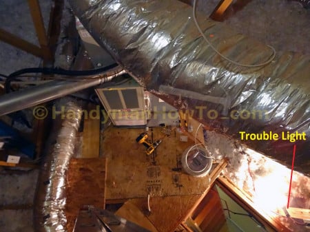
An interesting view from the extension ladder in the attic, looking down on the roll of NM-B 14/2 cable and folding attic stairway. The trouble light is plugged into the old electrical outlet by the stairway.
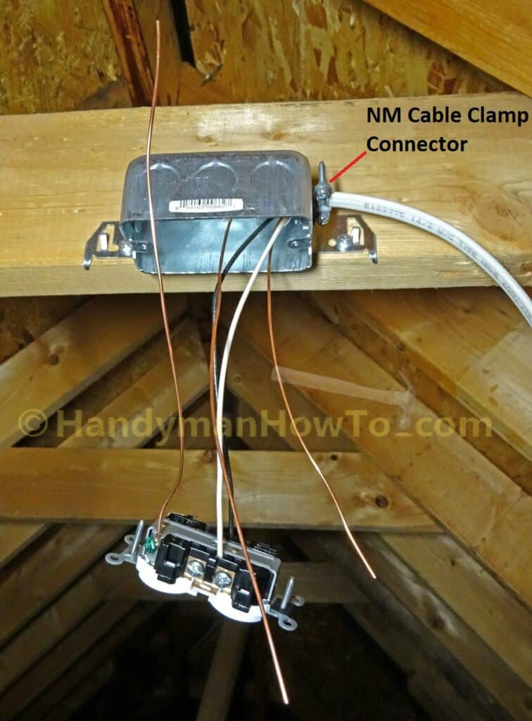
Attic Electrical Outlet Back Wire and Ground Connections
The NM-B 14/2 cable is inserted through the NM cable clamp connector so at least 1/4 inch of the outer insulation jacket is inside the electrical box, then the two clamp screws are tightened snug to hold the cable. Don’t over tighten the clamp screws to avoid crushing the cable and damaging the insulation. The 15 amp heavy duty Leviton #5252 duplex outlet features back wire connections, which I like for the ease and robustness of the connection. If you’re using a different outlet, follow the manufacturer’s wiring instructions.
I like to make my wiring connections on the “long” side and trim to length as needed, always being sure to have a least 6 inches of wire inside the box that extends at least 3 inches beyond the electrical box as required by NEC 300.14. Remember, wires never get any longer.
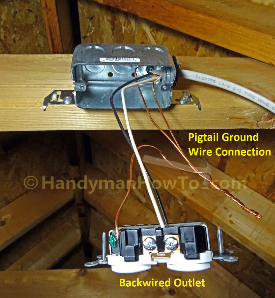
The three ground wires:
- Electrical box ground
- Duplex outlet ground
- Supply cable ground
are twisted together with lineman’s pliers:
and secured the ground wires with a wire nut:
Take care to use wire nuts rated for the wire size and number of conductors. I’m using the Ideal 76B wire nuts suitable for a minimum of two 14 gauge and maximum of four 12 gauge solid wires.
Looking up from the attic stairway at my progress. I’m using a battery powered lantern for the ladder work:
Fold the wires into the outlet box taking care not pinch or kink the wires, then mount the outlet to the steel box with the outlet screws:
The NM-B 14/2 is supported by NM cable staples installed:
- Within 12 inches of the steel outlet box with a clamp connector
Note: The staple must be placed with 8 inches of plastic box if you’re using one - Staples spaced not more than 4-1/2 feet apart
- Staple the cable flat at least 1-1/4 inches from the edge of the framing
The new attic light toggle switch, duplex electrical outlet and 4 inch square steel electrical box are prepared for installation in the next part of this series.
Take care,
Bob Jackson