Panasonic WhisperFit EZ fan old work ceiling mount and junction box wiring: Install the Flex-Z Fast metal bracket, wire the fan, connect the duct and mount the fan. This project is continued from Panasonic Bathroom Vent Fan Electric Cable Fishing.
Project Series Index
The fan installation is covered in a four part series:
- How to Install a Panasonic WhisperFit EZ Bathroom Fan.
- Panasonic Bathroom Vent Fan Electric Cable Fishing.
- Panasonic WhisperFit EZ Fan Old Work Ceiling Mount and Junction Box Wiring. (You are here.)
- Panasonic WhisperFit EZ Fan Installation – Wall Switch Wiring.
Flex-Z Fast Mounting Bracket
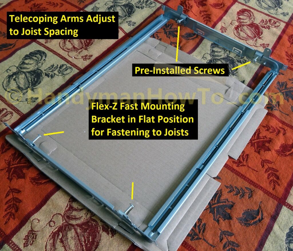
The WhisperFit EZ FV-08-11VFL5 includes the Flex-Z Fast metal bracket (see the fan installation instructions) which telescopes to fit between the joists. It’s a very nice system that avoids making a wood mounting frame for “old work” (replacement/retrofit/upgrade) situations:
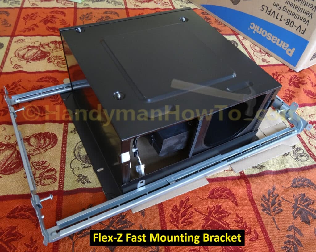
The Flex-Z Fast bracket arms telescope to fit the joist spacing and includes 4 pre-installed self-tapping wood screws:
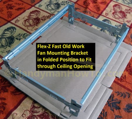
The bracket folds to fit through the ceiling opening:
Panasonic WhisperFit EZ Fan Old Work Ceiling Mount and Junction Box Wiring
Orient the Flex-Z Fast bracket in the “Up” position as stamped on the bracket, fold the wings and insert it into the ceiling opening:
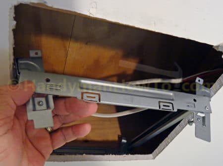
Lay the bracket on the ceiling and adjust to fit between the joists with the sides even with the ceiling opening:
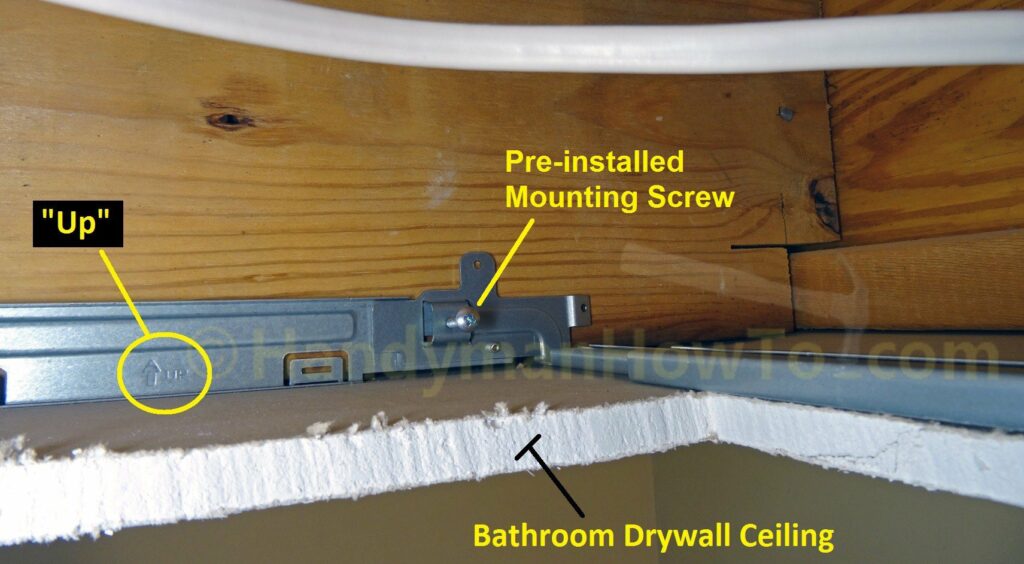
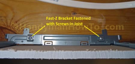
Then fasten the pre-installed screws to the joists. Easy peasy!
Panasonic WhisperFit EZ Fan FV-08-11VFL5 Junction Box Wiring
Electrical Safety: The electricity was shutoff at the circuit breaker at the start of the project. Always verify the electricity is Off before working on the wires.
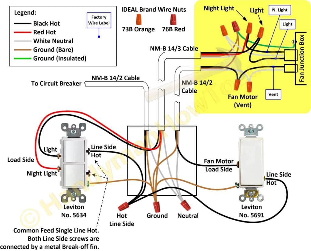
The next steps are highlighted in yellow on the wiring diagram:
Remove the junction box cover (it’s held in place by a small screw) and the 1/2 inch knockouts by bending back & forth with the tip of a screw driver. I chose to remove both knockouts for easier wiring. Then install two 3/8 inch non-metallic (NM) cable clamp connectors in the cover:
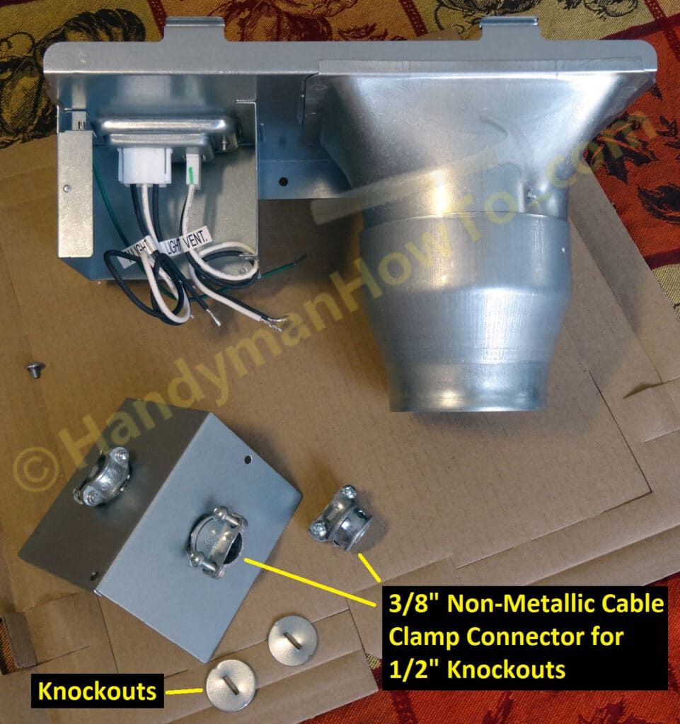
BTW – “non-metallic” (NM) cable clamps refers to the type of electrical cable (e.g. NM-B non-metallic sheathed cable) and not to the clamp itself which is steel.
Back on the stepladder in the bathroom, the two cables are inserted in the clamps and tightened. The white cable jacket insulation must extend at 1/4 inch beyond the cable clamp (NEC 314.17) and give yourself about 6 inches of wire:
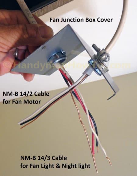
The next wiring steps are:
- Drive a pan-head screw about 1/2 inch deep into the subfloor above the bathroom ceiling.
- Wrap a ~18 inch long wire around the wood screw.
I used a length neutral white wire pulled from scrap NM-B 14/2 cable. - Loop the other end of the wire through a hole in the flange of the duct adapter.
The wire now holds the duct adapter near the ceiling so both my hands are free to wire the fan. - Trim the NM-B wires even if needed.
- The fan has pre-stripped stranded wires so you want to match those by stripping about 5/8 inch of insulation off the black (hot) and neutral (white) wire ends for the two-wire connections using the 73B orange wire nuts. (See the closeup photo below.)
- Twist and connect the NM-B 14/3 and 14/2 cables to the fan wires with wire nuts.
Refer to the fan wiring diagram above and the FV-08-11VFL5 installation instructions for details.
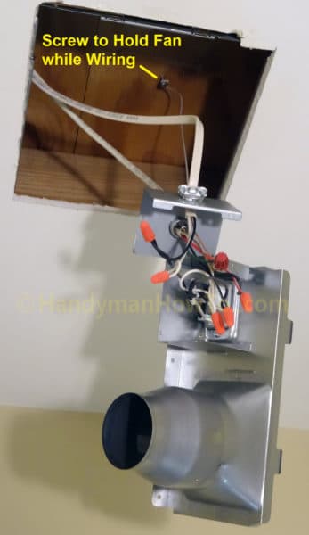
Closeup of the fan junction box wiring connections. Note that two types of wire nuts are needed:
- IDEAL brand 73B orange nuts for two wire connections.
Smaller orange nuts better fit the fan’s stranded-wire to NM-B 14 gauge solid-wire. - The three ground wires are connected with a larger IDEAL 76B red nut.
Twist the two NM-B 14 gauge solid ground wires together with pliers, then connect the green insulated fan ground wire to those with a nut.
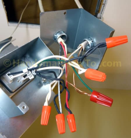
Gently fold the wires in the junction box then re-install the cover and screw.
Connect the Flex Duct
I have 4 inch diameter flex duct and didn’t need the 3 inch adapter. Remember to remove the shipping tape from the damper inside the exhaust cone:
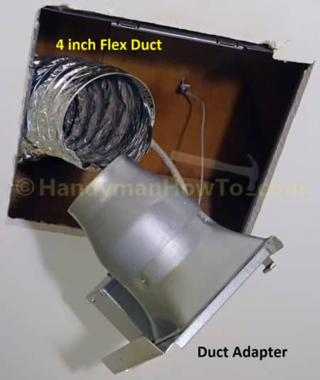
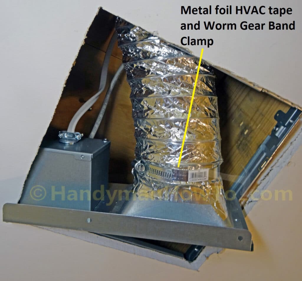
Place a worm gear band clamp over the flex duct, scoot the flex duct over the neck of duct adapter exhaust and seal it with metal foil HVAC tape. Do not use “duct tape” like the silly contractor did on the old fan. Next, position the band clamp over neck & flex duct, then tighten the band clamp with a screw driver:
Install the Duct Adapter to the Ceiling
Set the duct adapter in the ceiling being careful not to kink the flex duct and electrical cables. The duct adapter flange goes against the bottom of the ceiling:
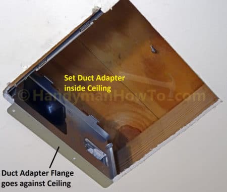
The duct adapter sitting between the 2×10 floor joists. The WhisperFit fans are low profile to also fit in 2×6 joist bays:
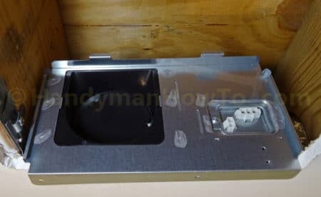
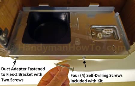
Fasten the duct adapter to the Flex-Z Fast bracket using the included self-drilling screws. The screws will “find” their way into the slot of the bracket:
Mount the Panasonic Fan to the Ceiling
The steps for installing the fan body are:
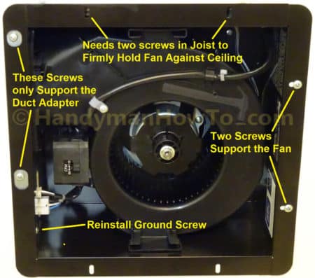
- Orient the fan body so the two large oval flange holes are on the same side (left in the photo) as the duct adapter.
- Slide the fan into the ceiling so it mates with the duct adapter.
- Fasten the fan body to the Flex-Z Fast bracket with two self-drilling screws.
The same screws are used to mount the duct adapter. - Reinstall the ground screw.
The ground screw holds the fan body to the duct adapter providing support. - Connect the two wire plugs to the duct adapter.
I noticed about 1/8 inch sagging on the left side of the fan flange. The duct adapter ground screw alone isn’t enough to hold the left side of the flange flush against the ceiling. I solved this by later installing two Simpson Strong-Drive #8 x 1-1/4″ screws set into the floor joist (top side of photo):
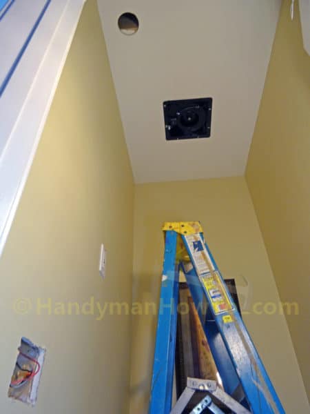
View of the fan mounted in the ceiling. Recall the round hole (top left in the following photo) was cut to pull a new run of NM-B 14/2 electric cable:
Install the Fan Light Kit
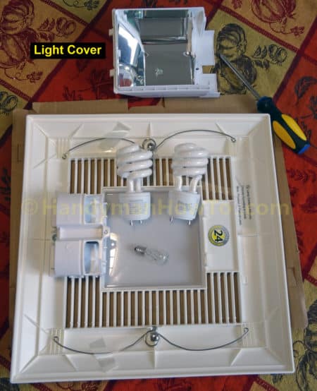
The WhisperFit EZ FV-08-11VFL5 fan has a primary light with two GU24 base (twist lock) light sockets, where I recommend using these 13 watt LED bulbs. Bulbs are included with the fan kit.
To install the light bulbs:
- Remove the light cover screw and cover.
- Install the three bulbs.
- Reattach the light cover.
Decide if you want the fan speed switch set to 80 or 110 Cubic Feet per Minute (CFM). I tried both settings and didn’t notice a significant difference in fan noise or air flow, so I set mine to 110 CFM.
Insert one grille spring into the fan body to hold the grill, connect the light unit plug then the other grille spring. Notice the two extra screws I installed in the joist (top of photo) to hold the fan flange flush with the ceiling:
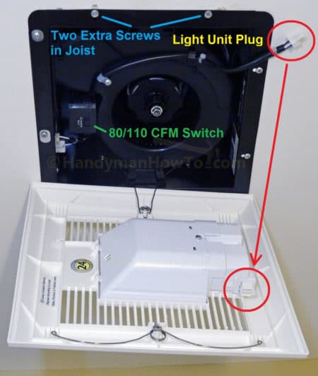
Adjust the grille slightly so it’s square with the walls.
This project is continued in Panasonic WhisperFit EZ Fan Installation – Wall Switch Wiring.
Thanks for reading,
Bob