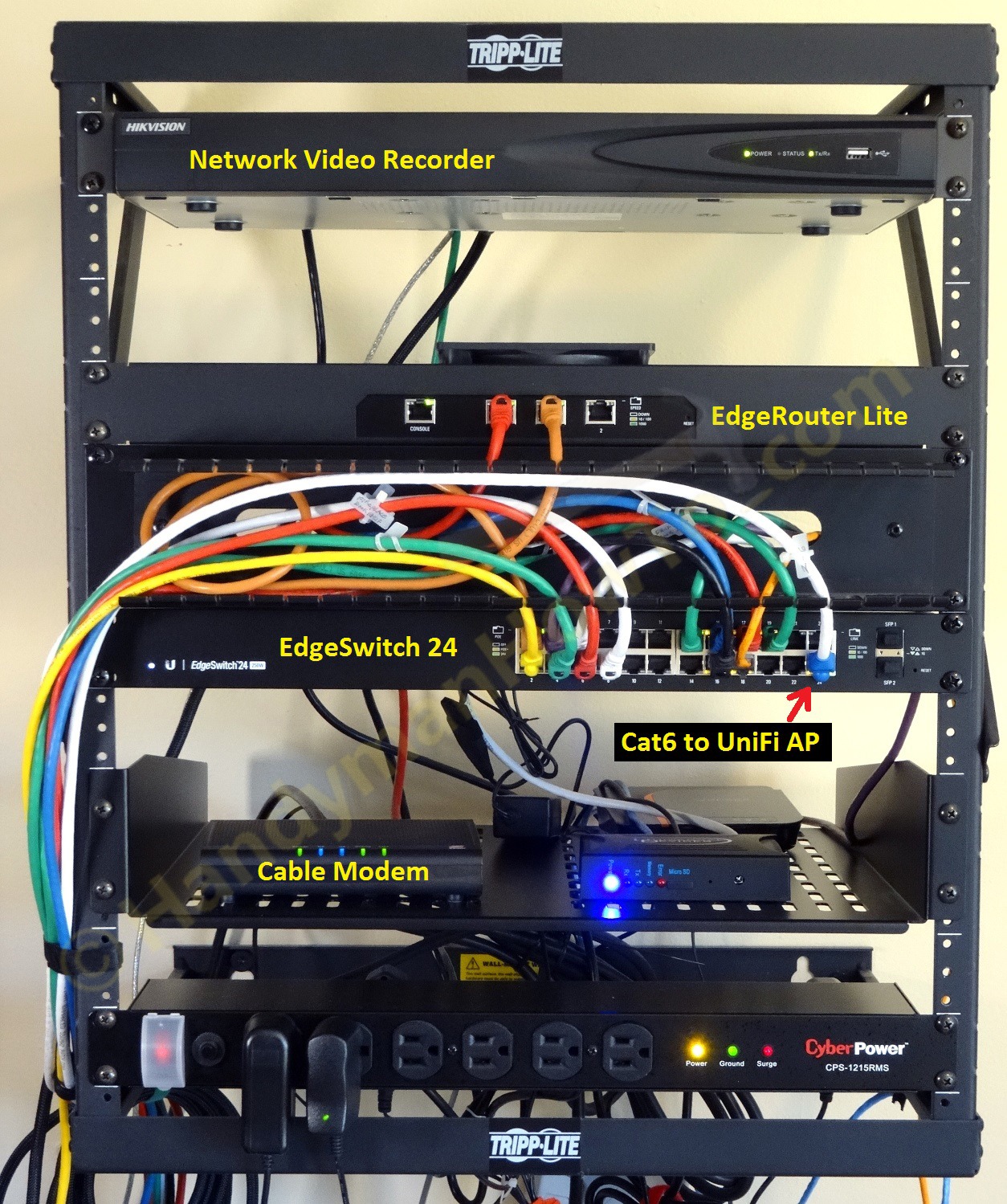
How to wire a Cat6 RJ45 Ethernet plug for a home network photo tutorial. This project is continued form How to Wire a Cat6 RJ45 Ethernet Jack.
How to Wire a Cat6 RJ45 Ethernet Plug
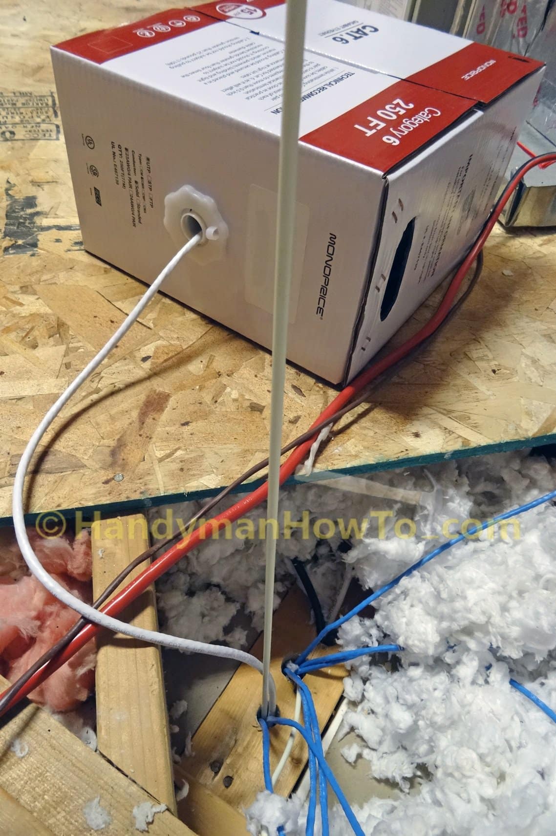
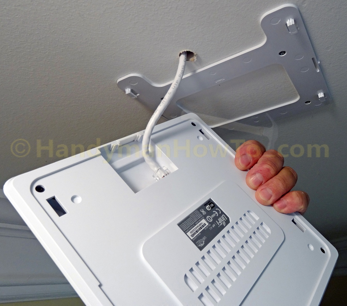
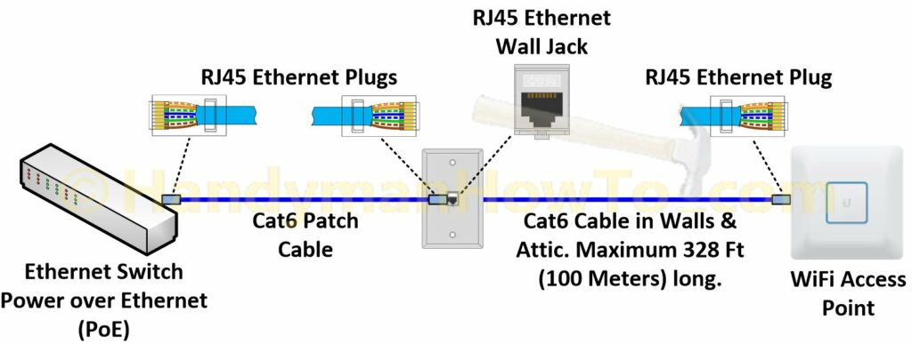
After fishing Ethernet cable from the attic and wiring a new Cat6 RJ45 wall jack, I needed to terminate the other end with a Cat6 RJ45 plug for the Wi-Fi Access Point (right side of the following diagram) and also make a Cat6 patch cable to connect the wall jack to my Ethernet switch (left side of diagram):
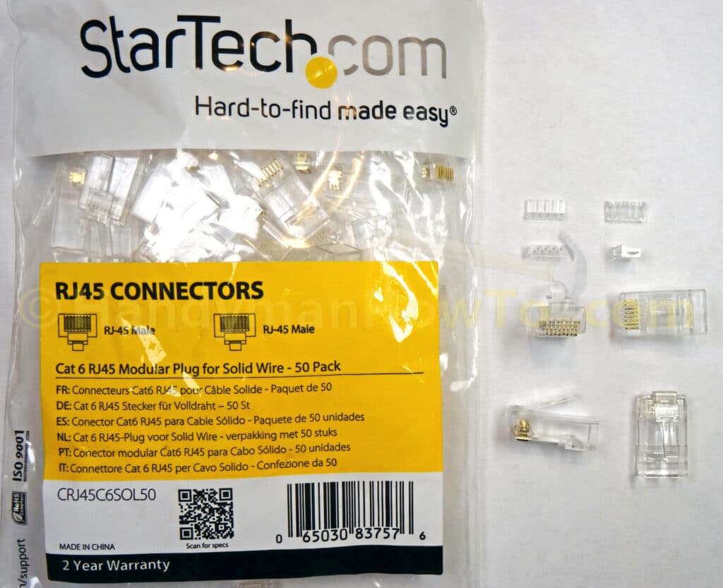
I purchased StarTech Cat6 RJ45 modular plugs for solid wire part #CRJ45C6SOL50:
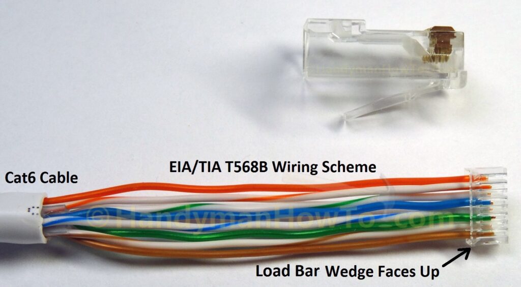
The StarTech Cat6 RJ45 plugs has two parts: 1) 8P8C modular plug and 2) load bars to accurately position the wires inside the plug:
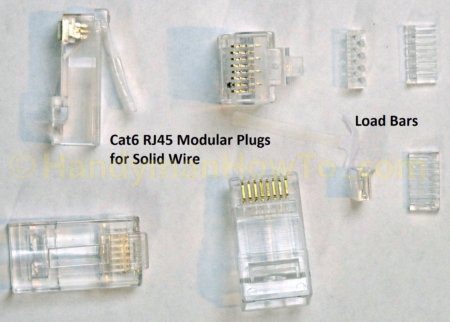
Because Cat6 cable has thicker 23 AWG wires and insulation compared to Cat5e cable, Cat6 wires would be too wide if laid flat in the 8P8C RJ45 plug. The load bar arranges the wires in a zig-zag pattern to align with the pins.
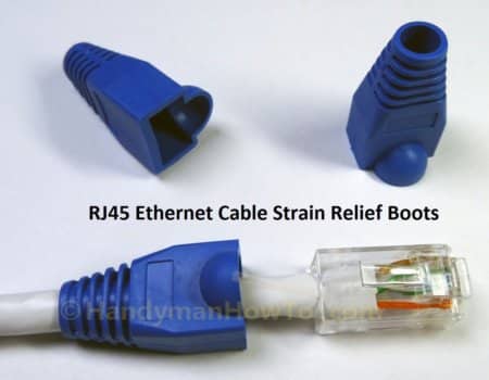
Cat6 Ethernet Plug Strain Relief Boot
If you plan on using strain relief boots, slide one over the end of the cable now because you cannot install a boot after the RJ45 plug is wired. I bought a pack of 25 boots.
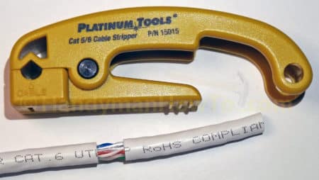
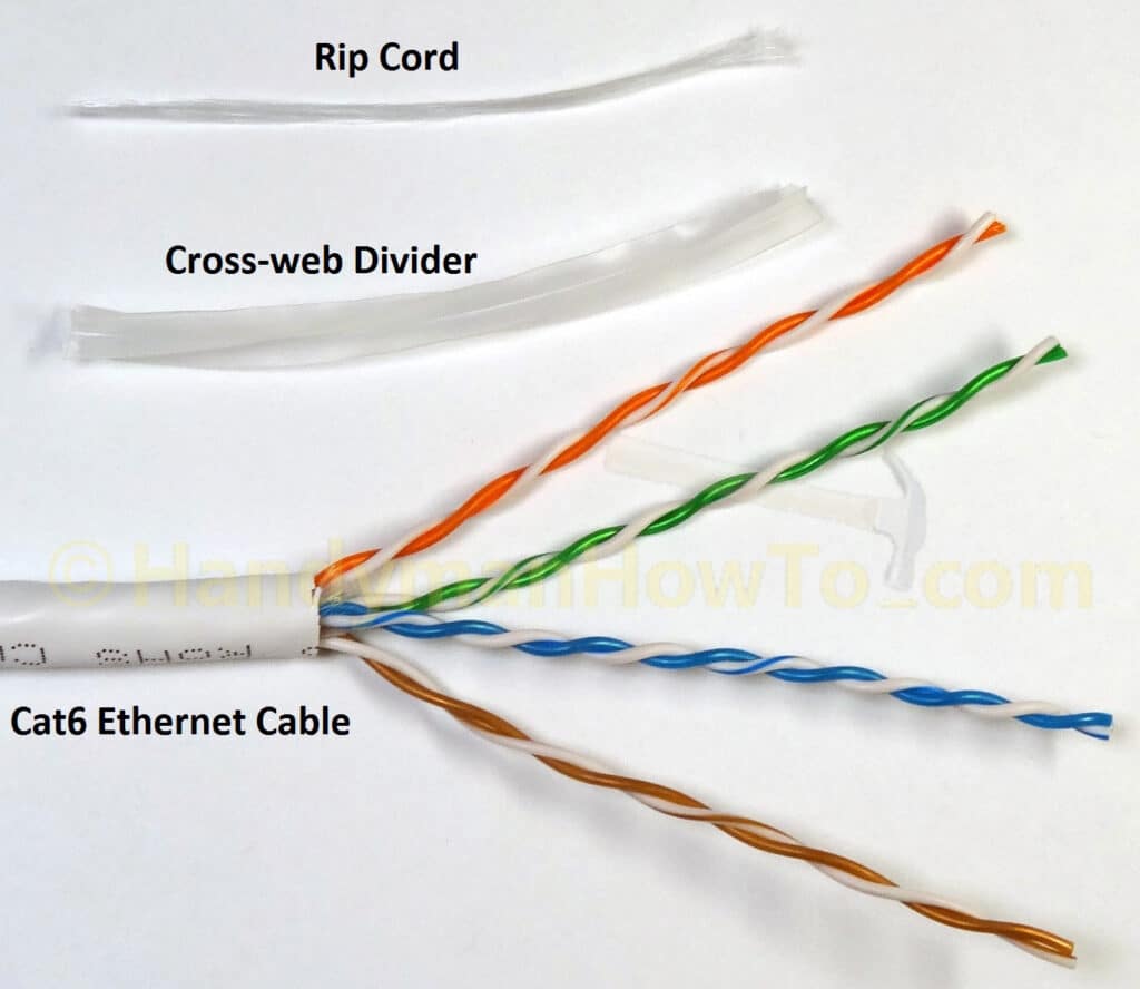
Strip the Cat6 Cable Insulation Jacket
Strip about 2 inches of outer insulation jacket with a cable stripper tool then cut off the silk-like rip cord and plastic cross web divider with scissors:
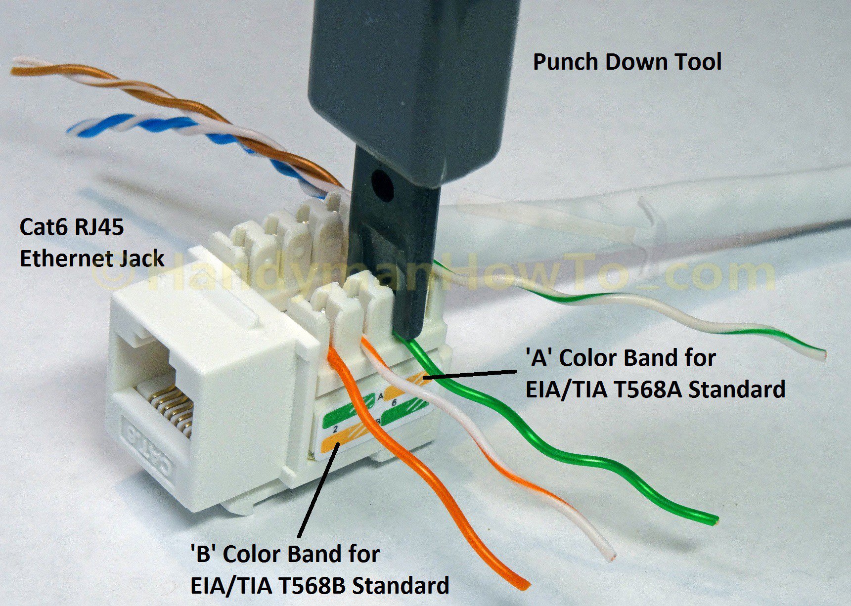
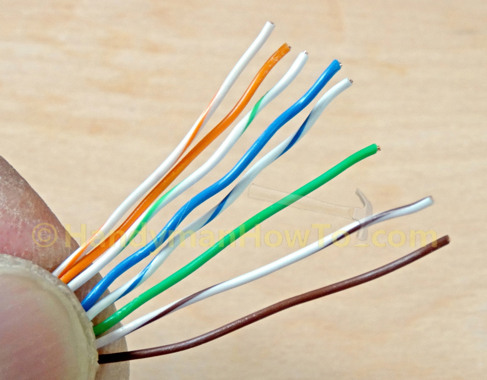
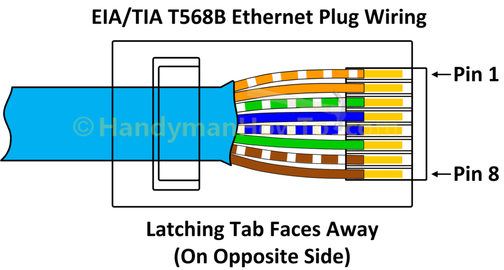
Unravel the twisted pairs and straighten the individual wires by drawing them several times between your finger and thumb. Hold the wires between your finger and thumb and arrange the wires per the EIA/TIA T568A or T568B wiring standard. See this tutorial details. The important thing is to wire both ends of the cable the same way. My home is wired per T568B which I’ll use here:
The wires will be a bit uneven after arranging the colors per T568A or B. Cut off a 1/4 inch with the RJ45 crimp tool so they’re even. Hold the wires near the end, double check the color arrangement then wiggle them into the load bar. Note the load bar wedge faces up. It looks tricky but the wires will find their respective positions without difficulty:
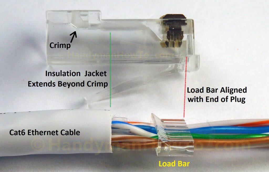
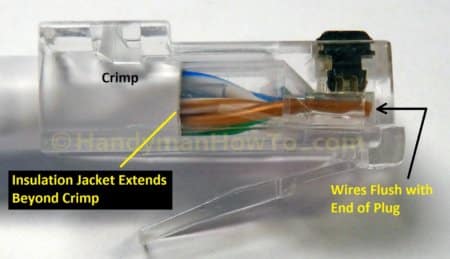
Slide the load bar down the wires. It works better to hold the end of the wires while pulling the load bar. Use the RJ45 plug to position the load bar such that the cable insulation jacket extends past the crimp tab:
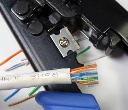
Cut the wires even with the face of the load bar using the crimp tool wire cutter:
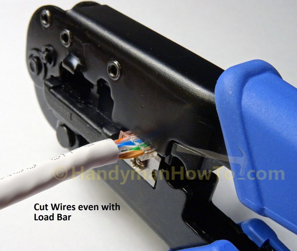
The wires are even with the load bar:
Insert the cable and load bar into the RJ45 modular plug. The plug latching tab faces down and the load bar wedge faces up. Verify the insulation jacket extends past the crimp tab and the load bar / wires butt against the end of the plug:
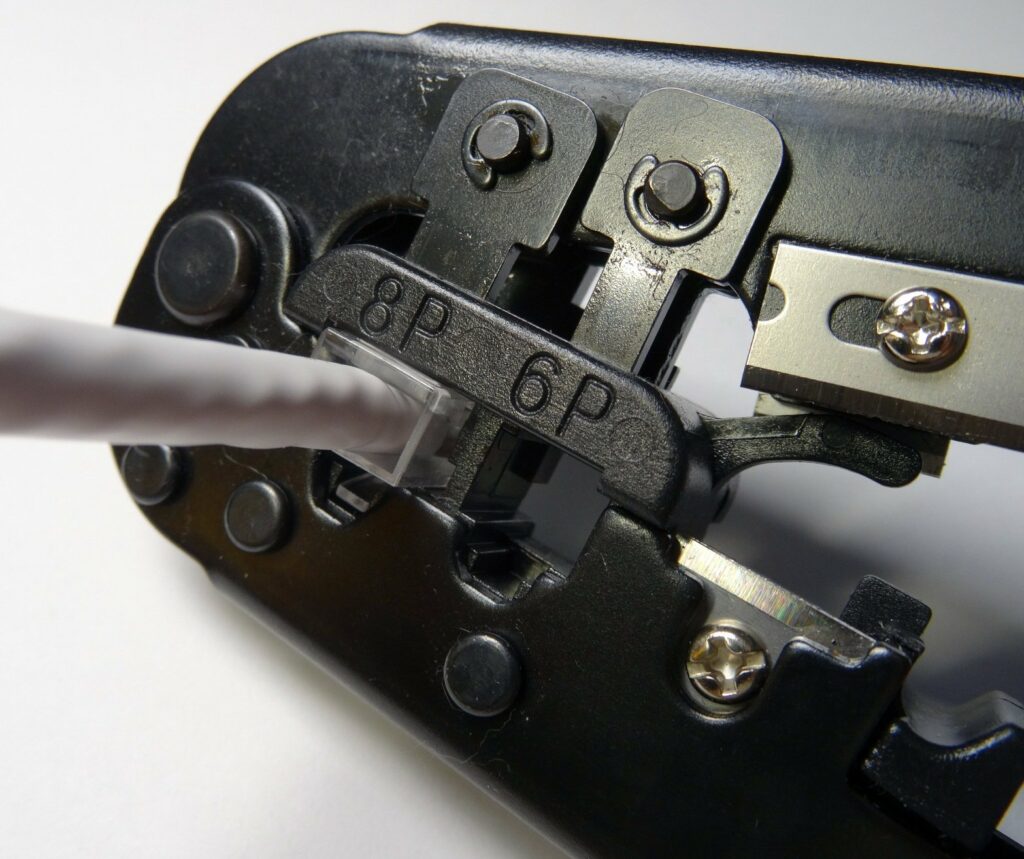
Crimp the RJ45 plug on the cable using the crimp tool:
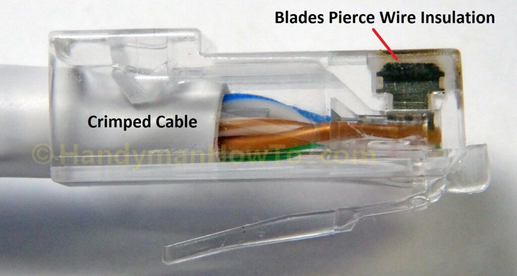
The crimp tab secures the cable and the blades have pierced the wire insulation:
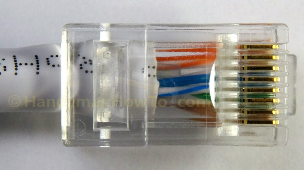
Another view of the wired Cat6 RJ45 plug:
After wiring both ends of the cable, I plugged the cable my Ethernet switch and tested it with my LinkSprinter 300.
Strain Relief Boot
RJ45 plug strain relief boots are optional but recommended. The strain relief boot must be slipped on the cable before installing the plug. Slide the boot over the plug, taking care to push down on the latching tab so it tucks inside the boot:
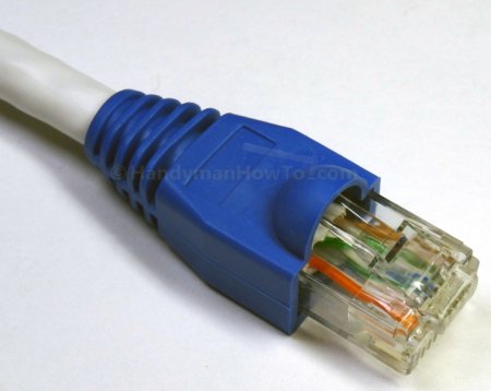
The completed Cat6 RJ45 plug with strain relief boot:
If making an Ethernet patch cable, wire a plug on the other end of the cable the same way.
Thanks for reading,
Bob Jackson