This tutorial shows how to replace a worn-out electrical outlet and explains best practices for wiring an outlet.
Electrical Outlet Hissing Noise
Electrical outlets are taken for granted until they don’t work. I started paying attention when the kids said the 1500 watt DeLonghi electric oil filled radiator space heater used to keep the bathroom extra warm wasn’t working. I checked the heater and there was no power, however I could hear a faint hissing or sizzling noise coming from the outlet. The heater plug was very loose in the outlet and the hissing noise changed as I wiggled the plug. I pulled the plug and the blades were pitted and corroded with a rough grayish film from electrical arcing and the plastic face of the outlet was melted slightly from the plug blade. A 1500 watt heater pulls 12 AMPS of current – and that’s a lot on a typical 15 or 20 AMP household circuit.
The problem was obvious: the electrical outlet was worn out from 10+ years of daily use. The metal contacts inside the outlet weren’t holding the heater plug securely and electricity was arcing across the slight gap between the loose plug and the outlet. The gap between the metal contacts causes electrical arcing – the sizzling or hissing noise – and a high resistance connection which heated the plug blades and melted the outlet face. If left alone, the outlet can get hot enough to start a fire.
I immediately replaced the electrical outlet with a new one and buffed the gray corrosion off the heater plug with some sandpaper. The space heater works great now.
I didn’t think to keep the worn out electrical outlet to show you here, thinking it was a rare circumstance not worth mentioning. However, as I inspected the most heavily used electrical outlets in the house I found several which were getting worn out and plugs were loose. The loose plug would often back out exposing the plug blades from the weight of the electrical cord. The bathroom and hallway plugs are the most used and abused. Think about everytime the vacuum cleaner is plugged into the hallway outlet and the cord is jerked and pulled to its full length as you work from room to room until the plug pops out. This stresses and opens the metal wipes inside the outlet over time causing a loose plug.
How to Replace a Worn-Out Electrical Outlet
This outlet by the bathroom sink was showing definitely signs of wear and wasn’t holding plugs securely. To replace the outlet, I began by:
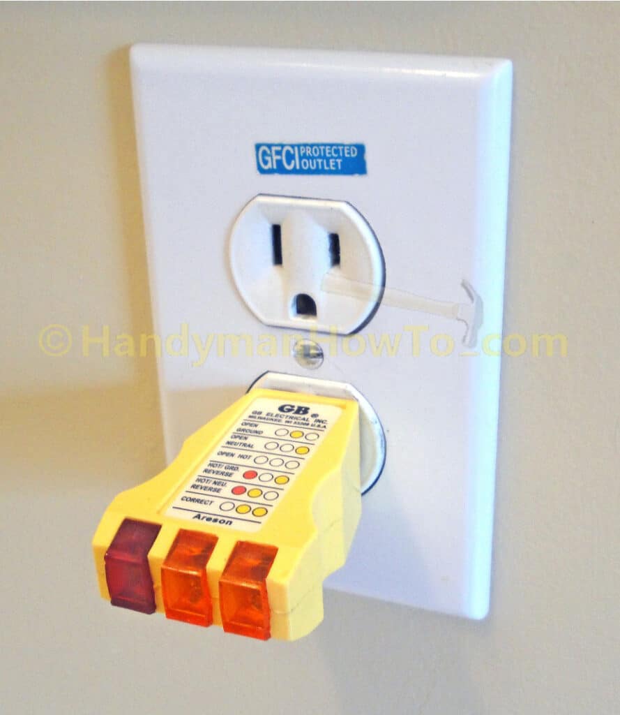
- Plugging in the receptacle tester which illuminated two yellow lights indicating the receptacle is wired correctly.
- Shut off the electricity at the circuit breaker in the main electrical panel.
- Observed the receptacle tester lights are not illuminated confirming the outlet is not powered.
When using a receptacle tester, you must test the outlet before shutting off the power because no lights on the tester can indicate an “Open Hot” condition. I could’ve used my standard voltage tester here, but since I’m wiring a new outlet the receptacle tester is more convenient.
1. Remove the Old Electrical Outlet
Remove the faceplate screw and white faceplate, then remove the two receptacle mounting screws to release it from the wall box.
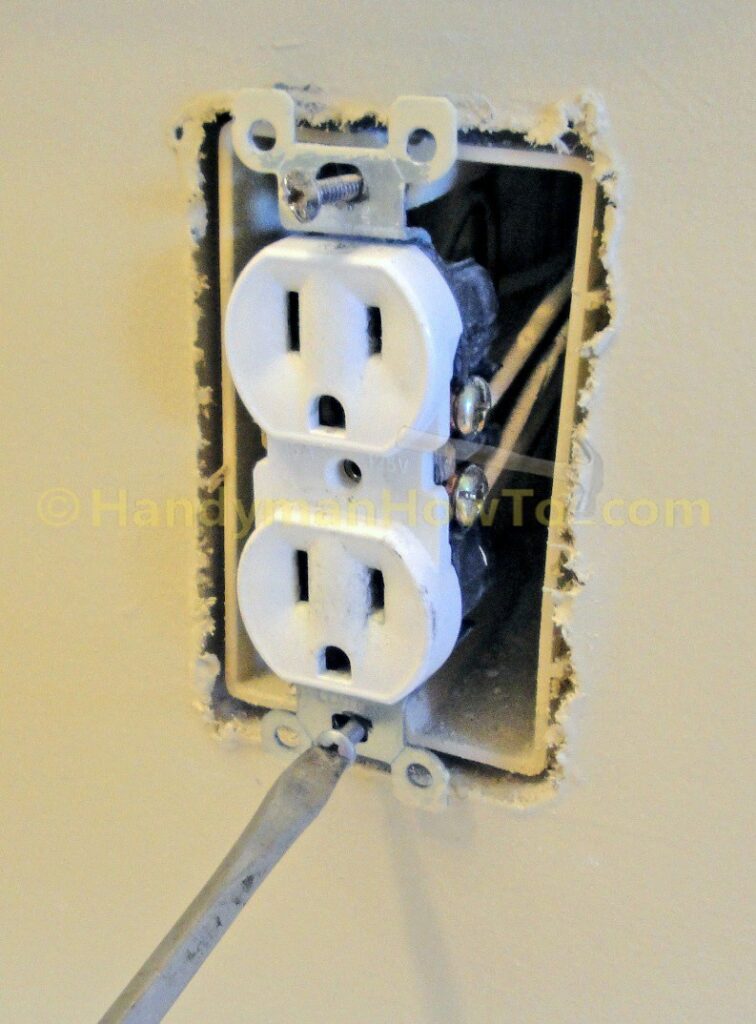
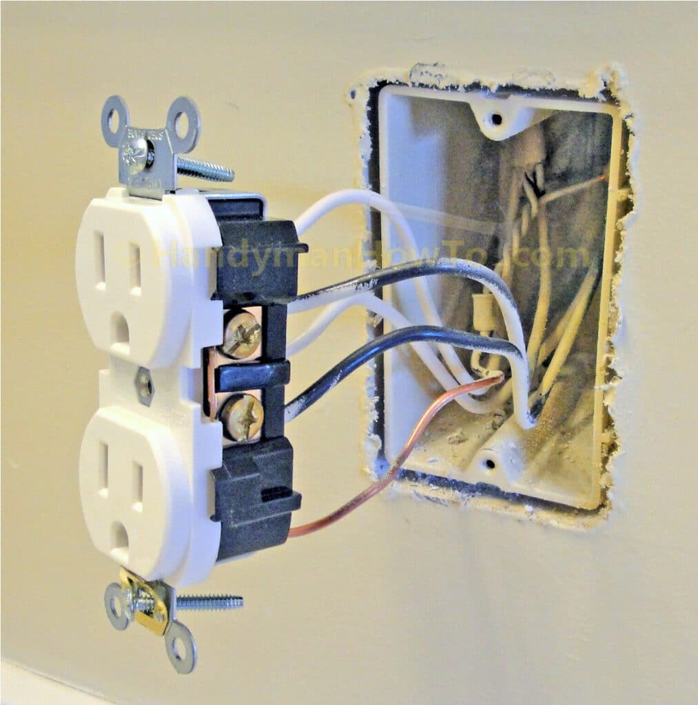
Pull the electrical outlet forward from the wall box to expose the wiring:
Several things are apparent from the way this outlet is wired:
- Because this outlet is in the bathroom, it’s on a 20AMP circuit with NM-B 12/2 (12 gauge, 2 conductor plus ground) wire protected by a Ground Fault Circuit Interrupter (GFCI) outlet (not shown) elsewhere in the circuit. 12 gauge wire is required for a 20AMP circuit.
- The outlet itself is rated for 15AMPs / 125 volts, this is fine and complies with the National Electrical Code.
- The outlet is “sidewired“, meaning the hot (black) and neutral (white) wires are fastened to the side screw terminals. (The black wires have some spray paint them from when the builder painted the walls.)
- The outlet is a “middle of the run” wired in “series” – meaning current passes between the side terminals to the next outlet down the line. This is common practice, but parallel wiring with a “pigtail” is better.
- The electrical wiring extends well beyond the minimum requirement of 3 inches beyond the wall box.
- The outlet is properly grounded via the bare ground wire that is tied via a pigtail to the cable ground wires.
In brief, this outlet is properly wired.
2. Series vs Parallel Electrical Outlet Wiring
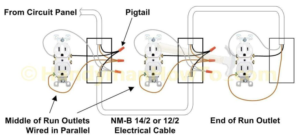
The following electrical outlet wiring diagram illustrates a middle-of-the-run outlet wired in series. The outlet in the above photo corresponds to the left and middle outlets in the wiring diagram. Series wiring is quicker and simpler compared to parallel wiring, however any problem with a middle-of-the-run outlet will affect all downstream outlets, i.e. outlets to the right of the bad outlet.
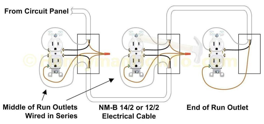
Wiring electrical outlets in parallel with pigtail connections that are twisted and nutted together is a more reliable method which isolates the outlet from the current path, thereby reducing the chance that a problem with the outlet will affect the other outlets on the circuit. Parallel outlet wiring is illustrated in this diagram:
3. Disconnect the Outlet Wiring
The wires can be removed from the worn out outlet by:
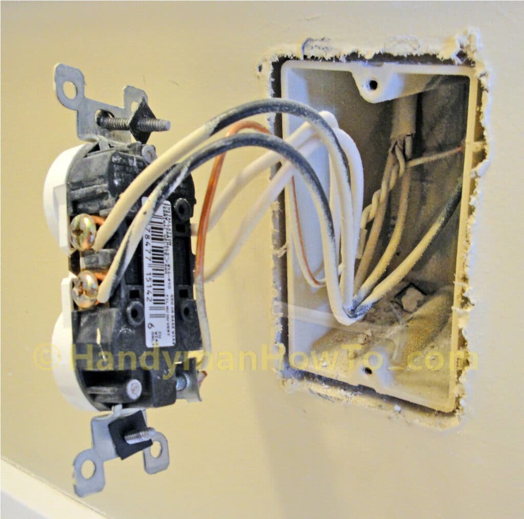
- Loosening the side terminal screws, opening the looped wire end with screwdriver tip and sliding it off the screw terminal. This is the preferred method if you’re going to sidewire the replacement outlet.
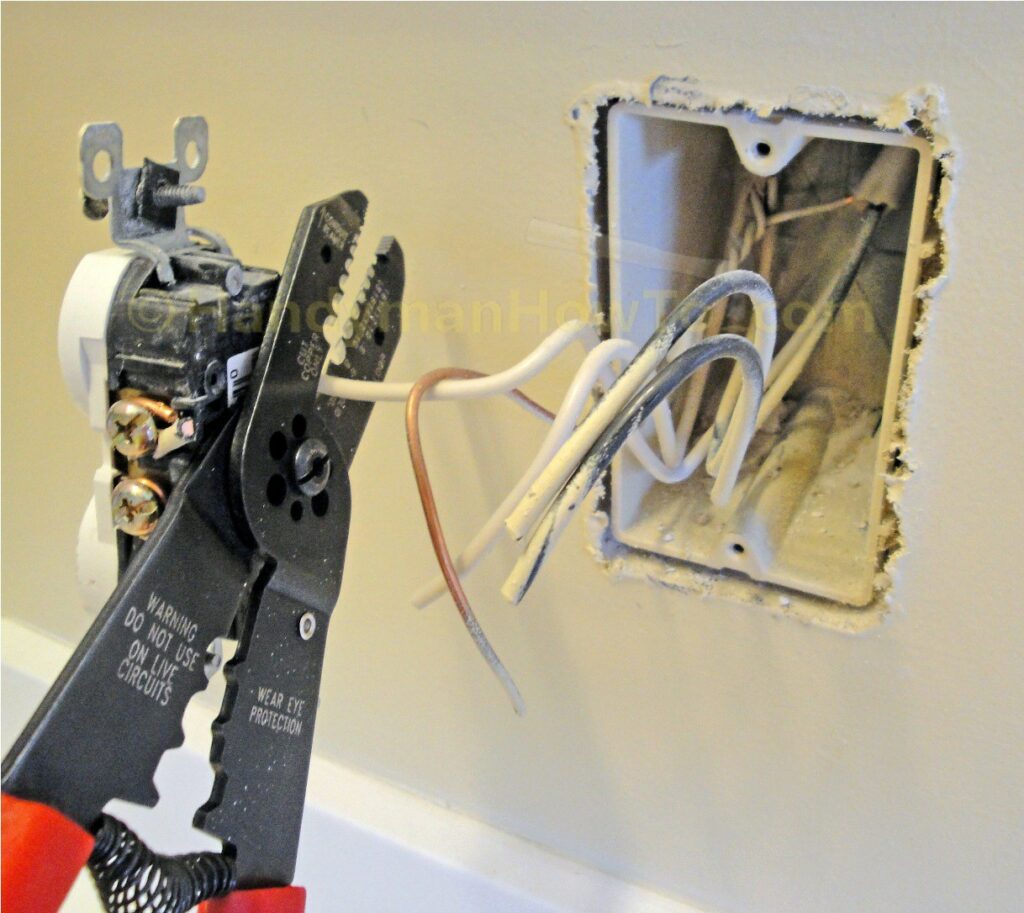
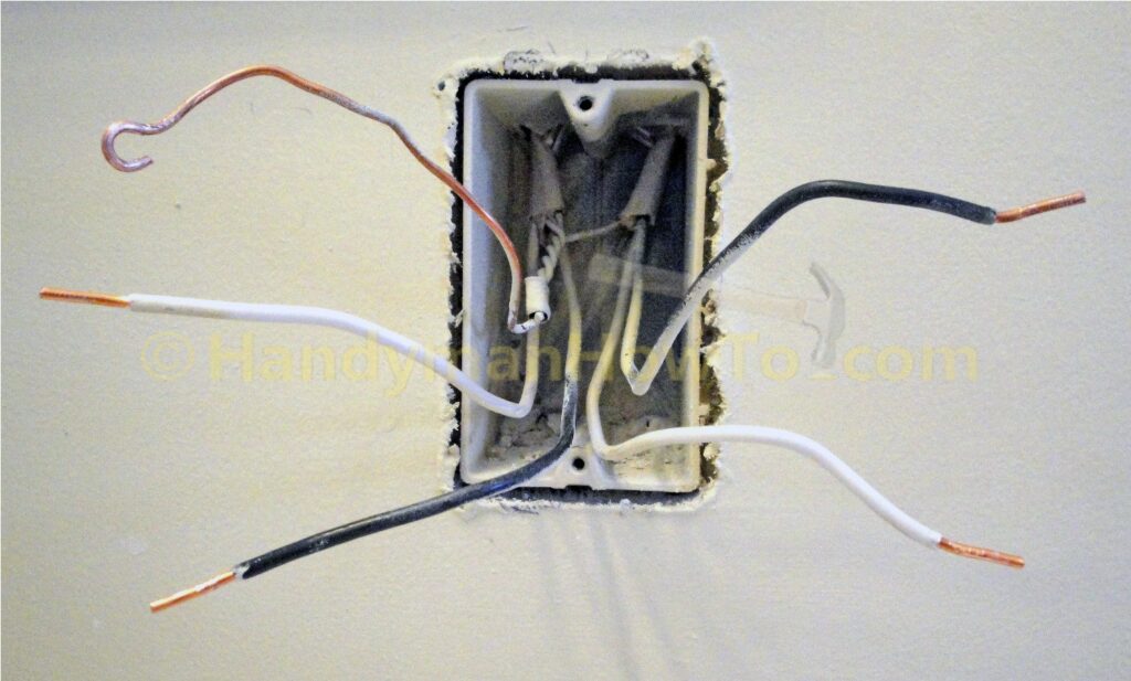
- Or simply snipping off the wires with wire cutters as shown here.
I chose to snip off the wires because I’m going to backwire the replacement outlet and I have plenty of wire extending from the wall box. Backwiring requires straight wire ends and I couldn’t be bothered to straighten the looped ends with pliers.
Do not cut your wires if the leads extend less than 3 inches beyond wall box.
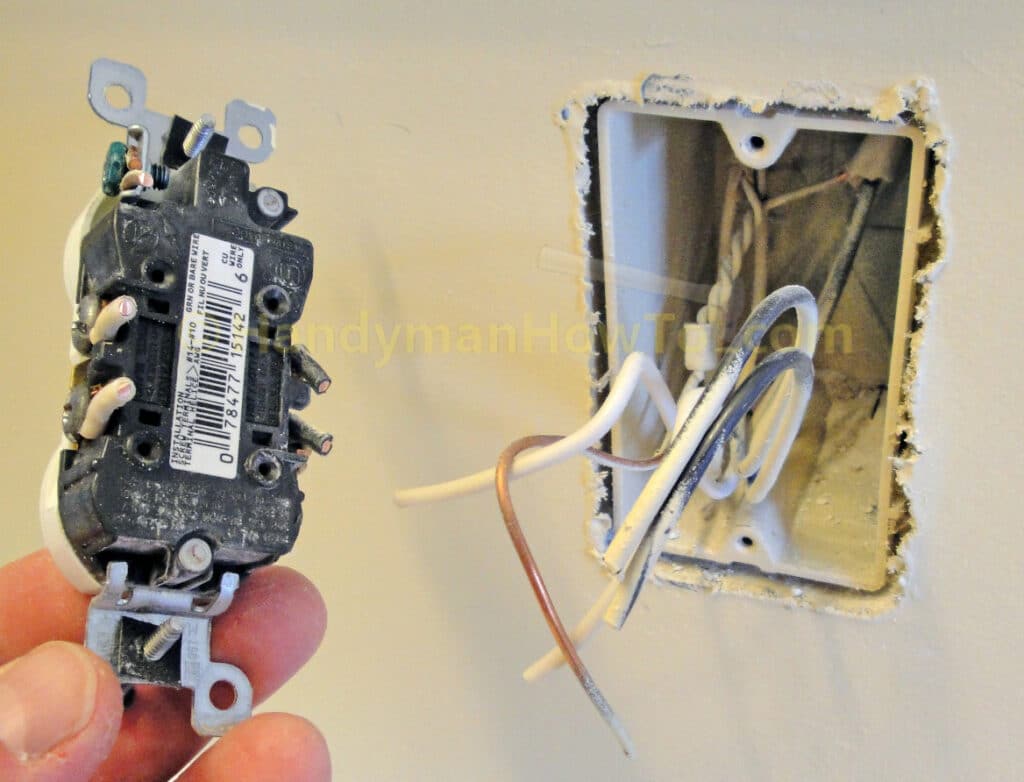
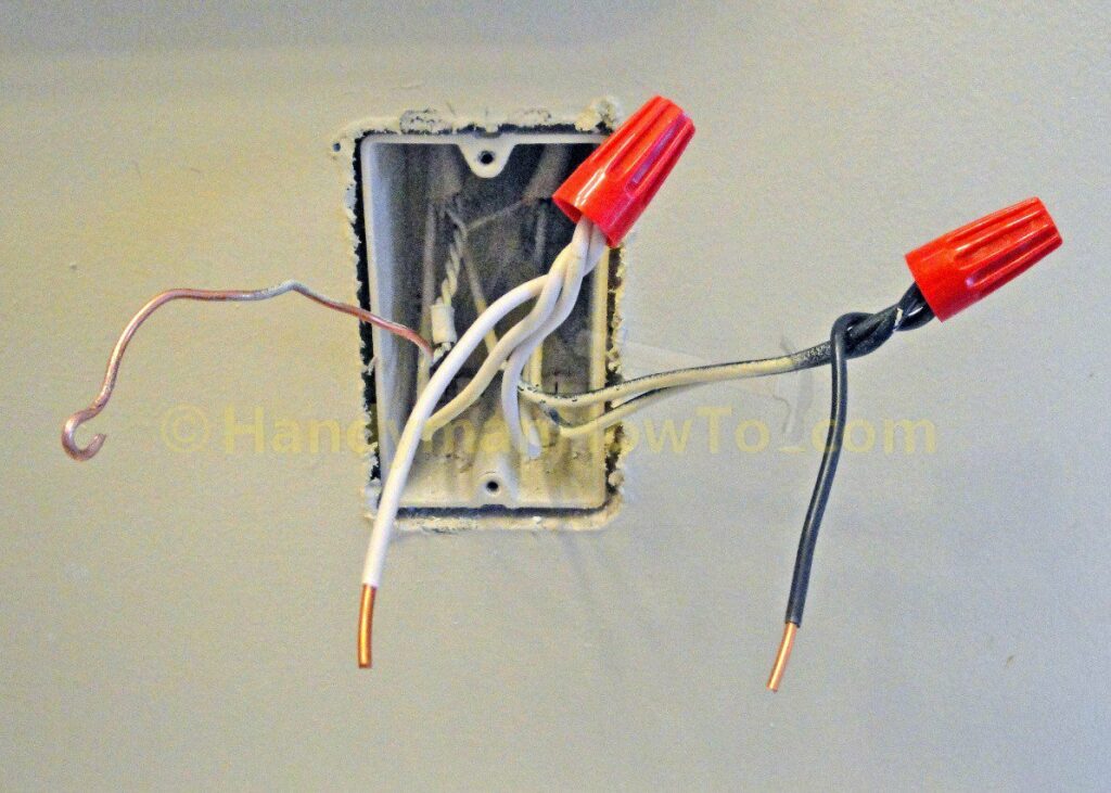
Electrical outlet after cutting off the wires.
4. Replace the Old Electrical Outlet
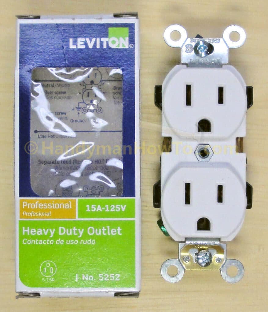
Having removed the worn out electrical outlet, I’ll replace it with a Leviton 5252-W Heavy Duty Electrical Outlet rated for 15AMPs and 125 volts for this high-use bathroom vanity location. The heavy duty outlet costs about $5 compared to less than $1 for the residential grade outlet. You get what you pay for in terms of quality and durability.
The following diagram explains the terminals and connections of an electrical outlet. I’m showing the Leviton 5320-WCP residential grade outlet because the side screw terminals are easier to see versus the heavy duty outlet above; however both outlets have the same configuration.
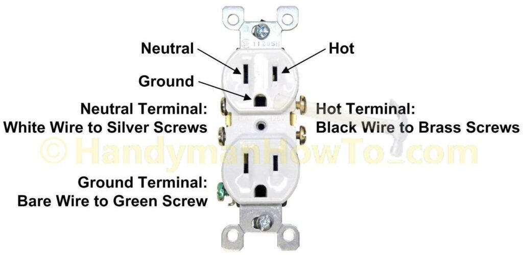
There is no “up” or “down” to an electrical outlet and it can be installed in the “face” orientation as shown above or rotated 180 degrees. I recommend sticking with the orientation used in your home for consistency.
5. Backwiring an Electrical Outlet
The new Leviton 5252 outlet will be backwired using the screw-and-clamp system of the heavy duty outlet. Backwiring is faster than sidewiring and just as secure with the screw-and-clamp system of the heavy duty outlet. To backwire the outlet, the 12 gauge wires are stripped to the length as measured by the strip gauge embossed on the back of the outlet.
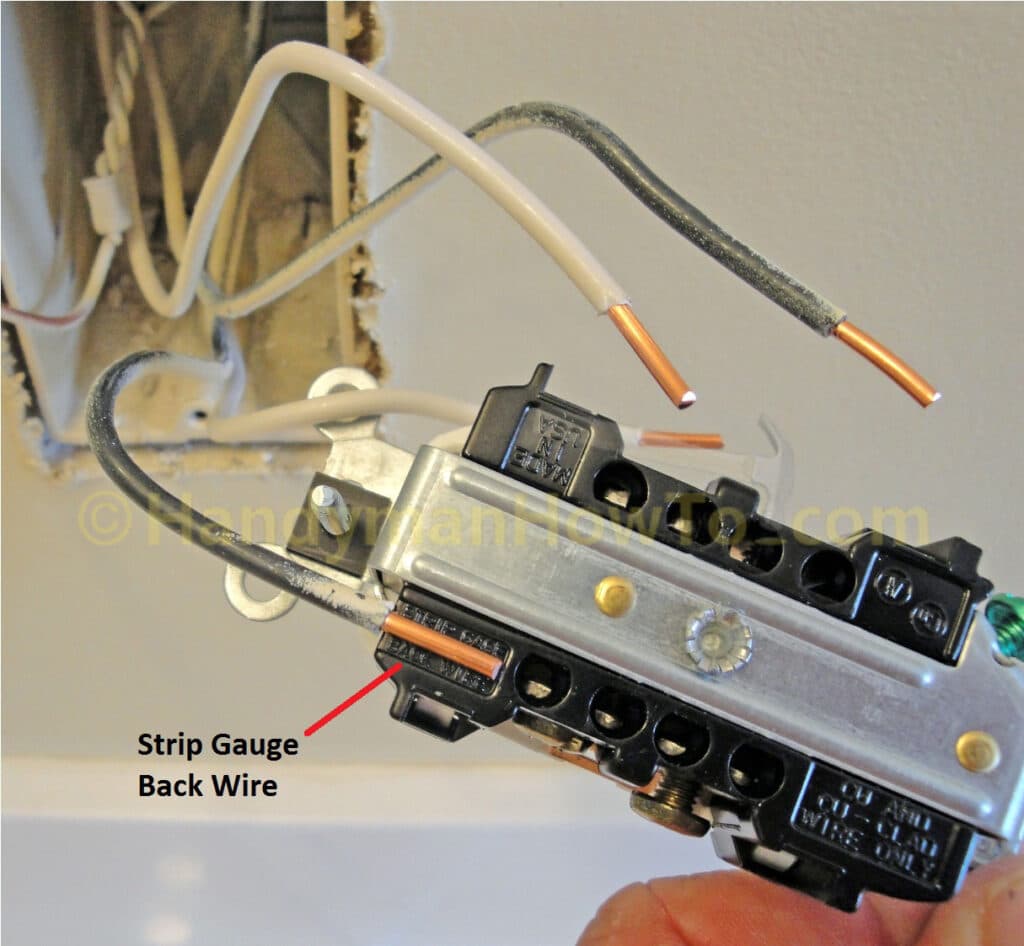
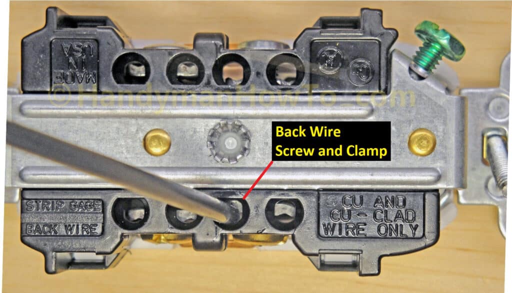
Here’s a closeup of the backwire method. The wire is inserted into the hole and captured by the silver colored clamp as the side screw is tightened. The clamp face is serrated for extra holding power and the wire will not rotate.
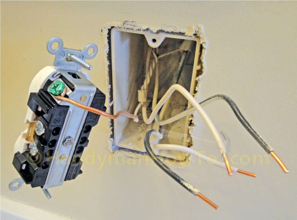
I like to wire the ground first for safety and convenience. The ground wire is looped around the green ground screw and the screw is tightened.
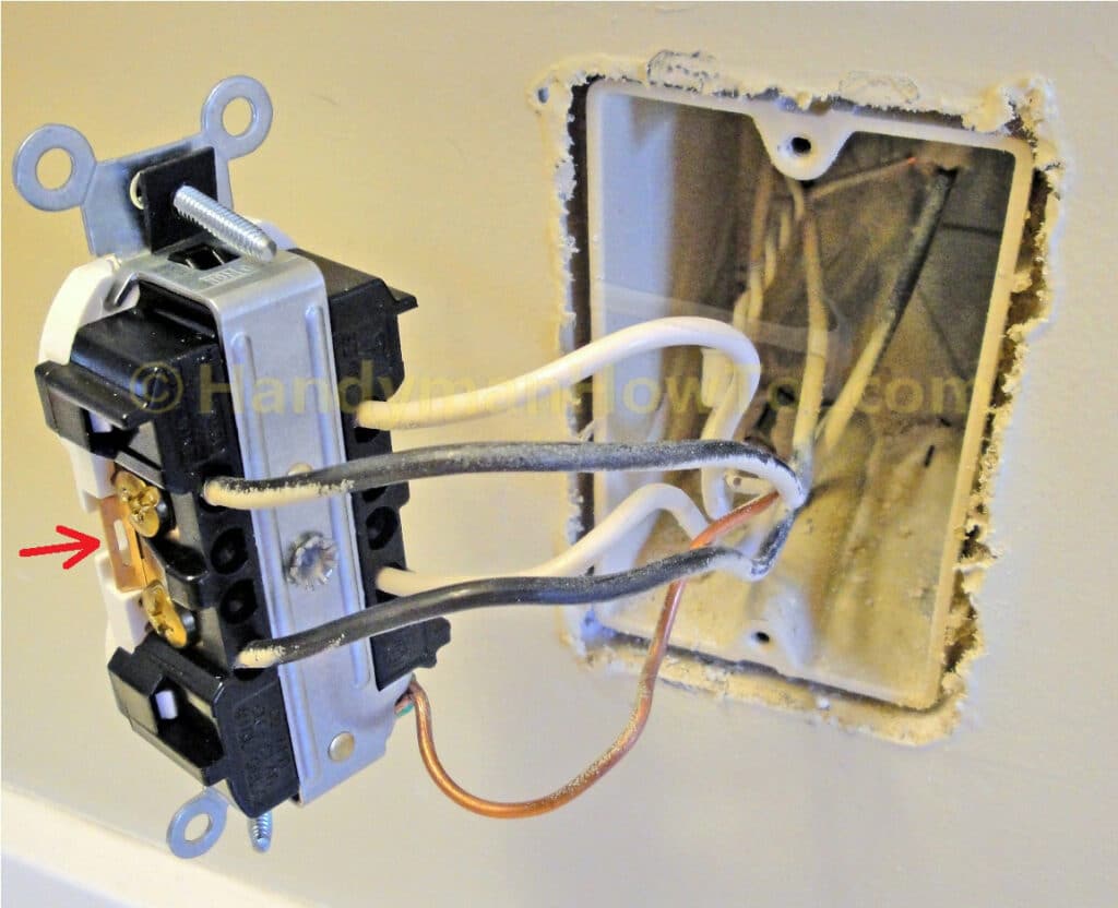
The hot (black) wires are inserted on the side with the brass colored screws and the screws tightened to clamp the wire in place. The white (neutral) wires are inserted on the side with the silver colors screws and secured. In a middle-of-the-run series wired configuration such as this, the current flows across the metal tab (red arrow) between the terminals to reach the downstream outlets. A problem with the outlet could affect all downstream outlets.
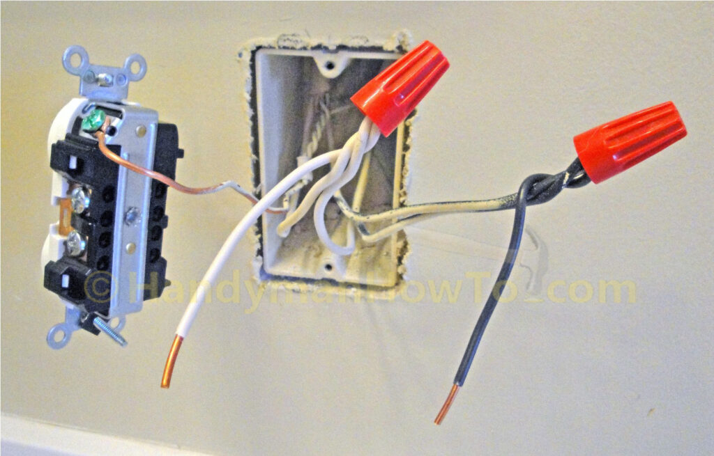
The backwired outlet is ready for mounting in the electrical box.
At this point all that’s left to do is gently fold the wires inside the wall box, fasten the two mounting screws and replace the outlet cover plate.
6. Electrical Outlet Pigtail Wiring Connections
I prefer wiring middle-of-run outlets in parallel with pigtail connections for improved reliability and fault isolation as illustrated in following the wiring diagram. Some local building codes require outlets to be wired in parallel for these reasons.
Rewiring an outlet from series to parallel is straightforward with two short lengths of wire and wire nuts for the hot and neutral pigtail connections. A pigtail connection is always used for middle-of-run ground connections whether wired in series or parallel.
Shut off the Electricity
Be certain to shut off the electricity at the circuit breaker panel if you haven’t already done so.
7. Wiring an Electrical Outlet in Parallel
To demonstrate wiring an outlet in parallel, I disconnected the new Leviton 5252 heavy duty replacement outlet which was backwired. That’s the neat thing about backwiring – it’s easy to install and disconnect the wires just by loosening the terminal screws.
An electrical is wired in parallel with pigtails by:
- Cut a 6″ inch length of black (hot) and white (neutral) wire for the pigtail splices.
- Strip 3/4″ inch of insulation the wires in the wall box and one end of the pigtail splice.
- Matching wire colors, twist the ends of the two black wires coming from the outlet box together with the 6″ black wire splice with lineman’s pliers. Twist the wires in a clockwise direction (right twist) with lineman’s pliers as shown. Secure the wires with a wire nut.
- Repeat the pigtail splice connection for the white (neutral) wires.
Note the bare ground wire is already on a pigtail connection via a metal bonding clamp. If you happen to be running wire to install a new middle-of-run outlet, be certain to make a pigtail connection for the ground wires.
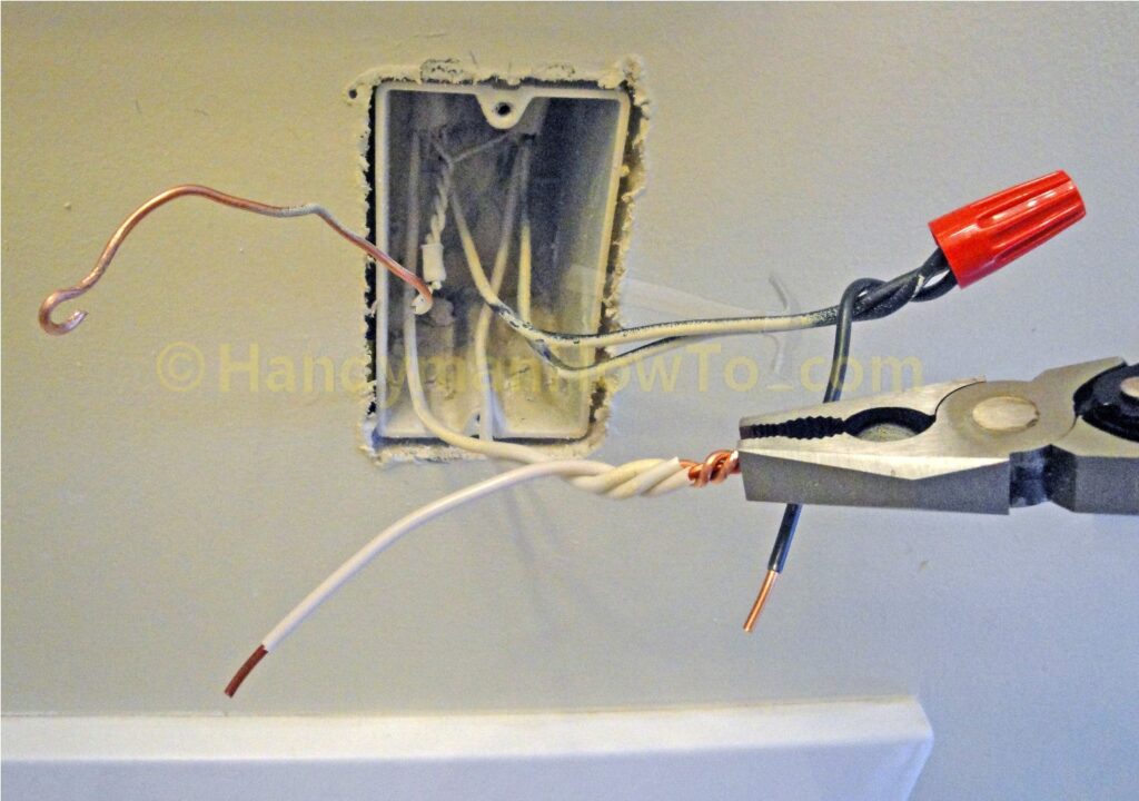
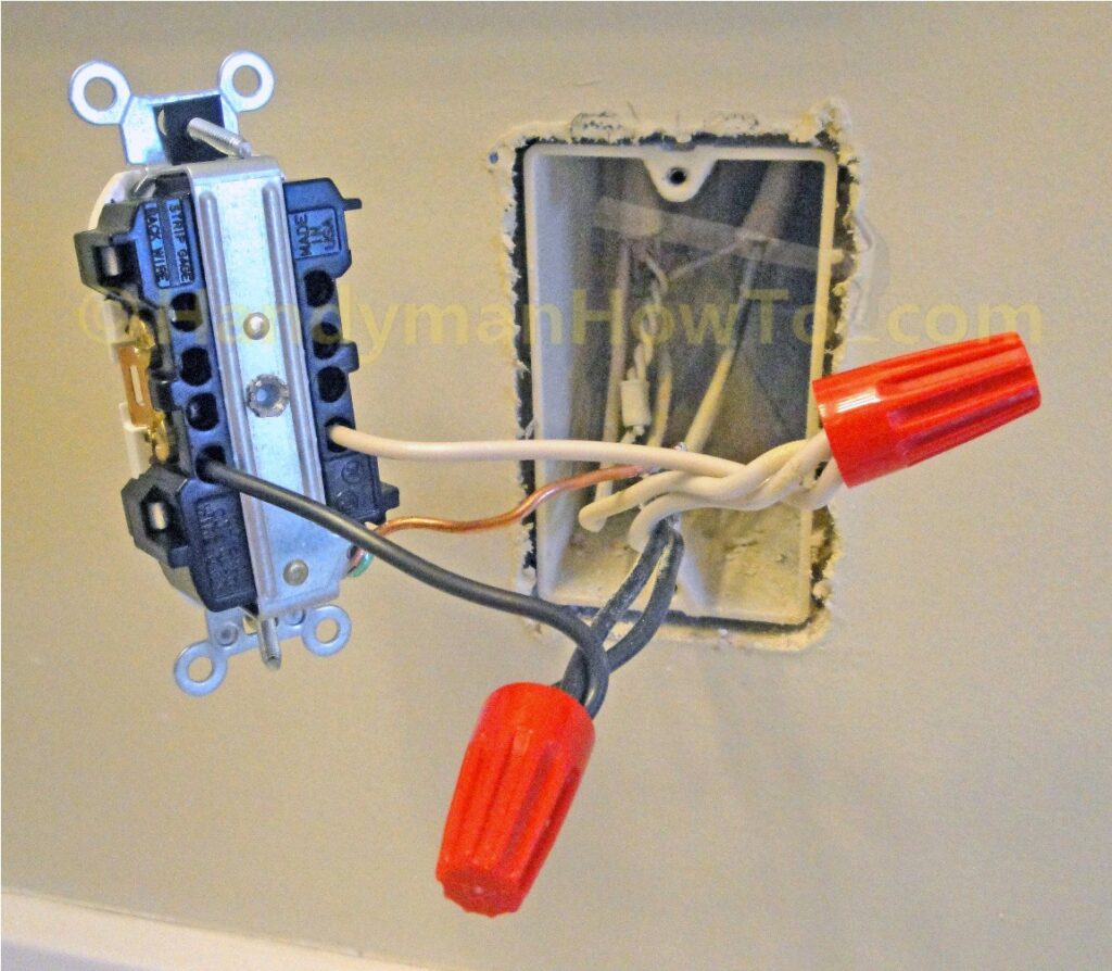
Pigtails wire connections are complete:
Use the strip gauge on the back of the electrical outlet to measure and strip the correct length of wire for the backwire connection.
The ground wire is looped around the green ground screw. Tighten the screw really well to secure the connection.
Backwire the outlet by:
- Loosening the side screw to expand the internal clamp.
- Insert the black (hot) wire in one of the backwire holes on the side with the brass color screws. Any of the four backwire holes will do. Take care the wire is inside the jaw of the metal clamp.
- With the wire fully inserted, tighten the side screw to clamp the wire in place.
- Insert the white (neutral) in a backwire hole on the side with the silver screws and secure it by tightening the screws as before.
- Check the wires are secure by giving the wires a pull. The wires should be held fast with no “give” or rotation.
Carefully fold the wires into the electrical box using gentle loops. 12 gauge wire is much stiffer than 14 gauge and getting all the wires folded in can take some attention to detail. Make sure the bare ground wire is not touching the side screw terminals.
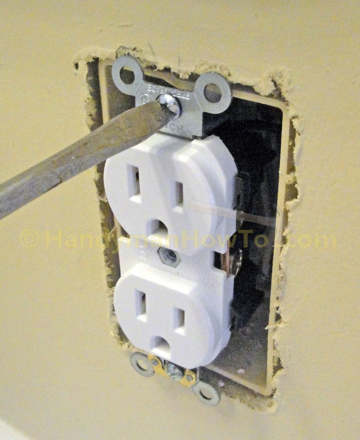
When the wires are in the box, mount the outlet to the wall box with the two mounting screws.
The old outlet wallplate will be replaced with a Leviton Nylon Wallplate for a new and neat appearance.
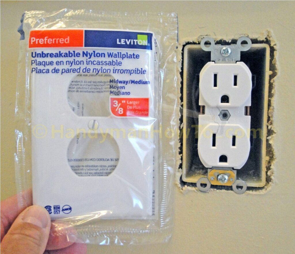
A “GFCI Protected Outlet” sticker is affixed to the wallplate (you get these when you purchase a GFCI outlet – I had some left over from the basement bathroom project).
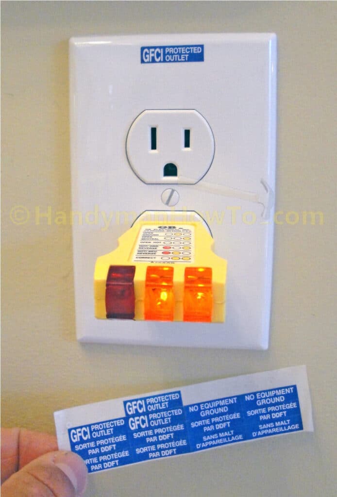
The receptacle shown in the above photo doesn’t have the GFCI test button. I later purchased GFCI receptacle tester: plug it in, press the small button and it’ll create a “safe ground fault” to trip the GFCI and shutoff power to the circuit. That way you know the GFCI outlet (not shown) or GFCI circuit breaker is working correctly. Of course, you’ll have to press the Reset button on the GFCI outlet or reset the GFCI circuit breaker after testing the outlet.
I turned on the circuit breaker at the main electrical panel and verified the outlet is correctly wired with the receptacle tester. Everything is correct.
8. Worn-Out Electrical Outlet Teardown
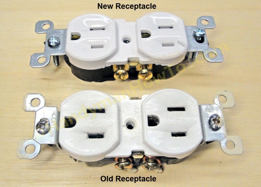
The old electrical outlet that was getting worn out with loose plugs is a Leviton Residential Grade Electrical Outlet, Model #: 5320-WCP. The outlet served well by bathroom vanity for about 10 years before wearing out. For 59 cents, it’s a testament to the success of mass production and maximum quality at a low price.
A new and old Leviton 5320-WCP receptacles are shown here for comparison. Some pitting around the receptacle face can be seen on the old outlet.
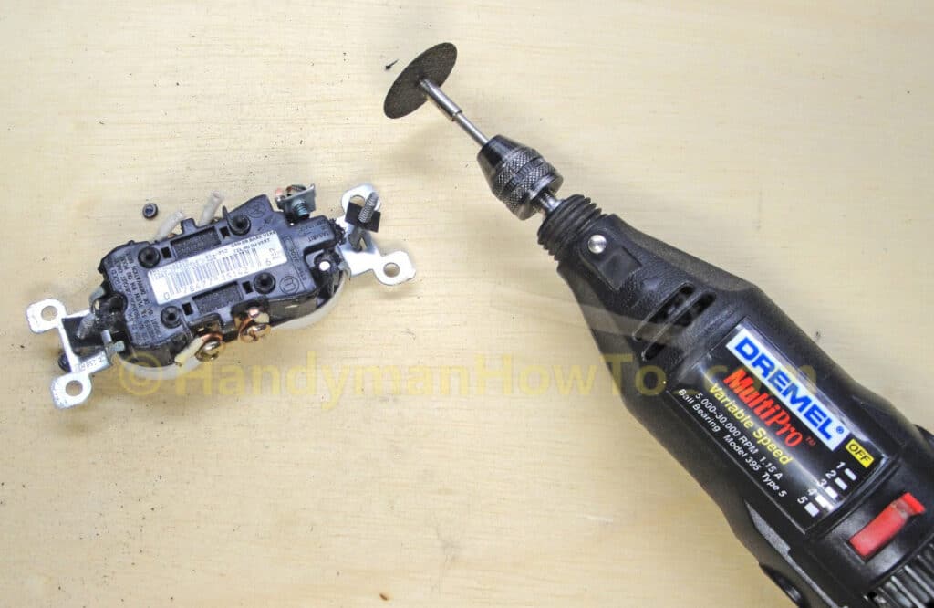
The old receptacle is held together by two metal rivets on the back. I cut off the rivet heads with a Dremel tool cutoff wheel.
The main problem with the old receptacle is it wasn’t holding a plug because the U-shaped contacts (yellow arrows) were getting worn out. These U-shaped contacts – also called “wipes” – fatigue and open up over time through repeated use when plugging in appliances.
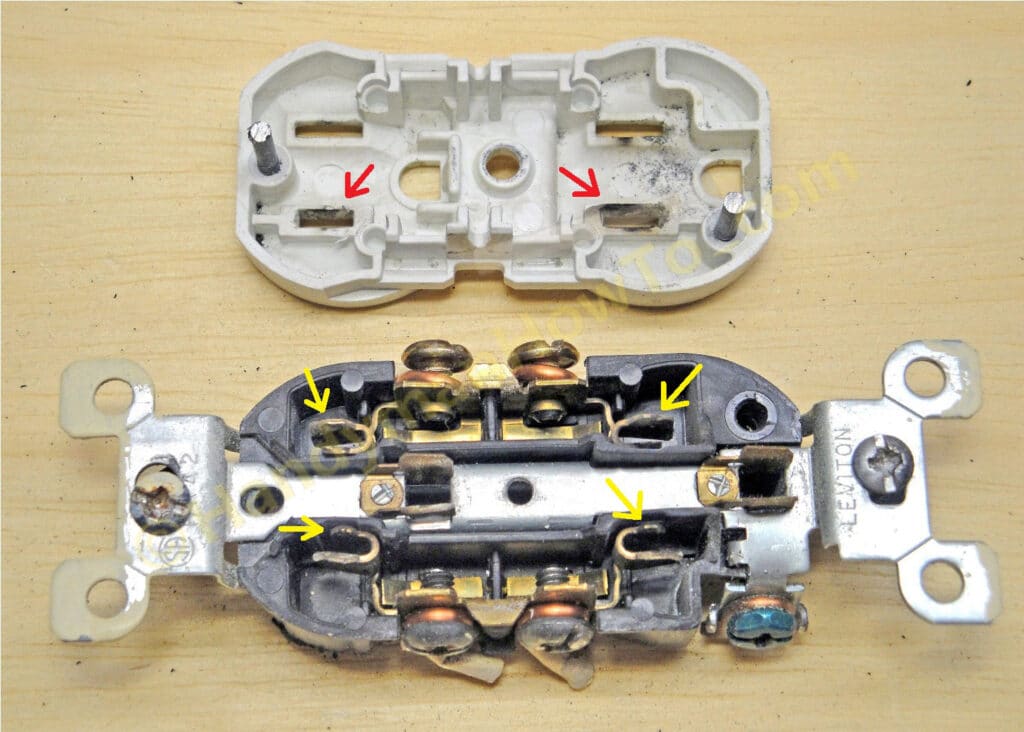
As the contacts open up, the plug becomes loose resulting in a high resistance connection, causing overheating, arcing and corrosion. If the outlet isn’t replaced, the connection can become so bad that constant a constant sizzling or hissing noise is heard from the electrical arcing as happened with that outlet I described in Part 1.
Be safe,
Bob Jackson