My garage has a motion sensor floodlight on the corner by the driveway. I upgraded the garage floodlights by:
- Install an Insteon In-LineLinc Relay for home automation.
- Add a 2nd slaved floodlight at the other end of the garage. The slaved floodlight operates with the primary motion floodlight under control of the In-LineLinc.
The details are given in this wiring diagram – click to view a full size image.
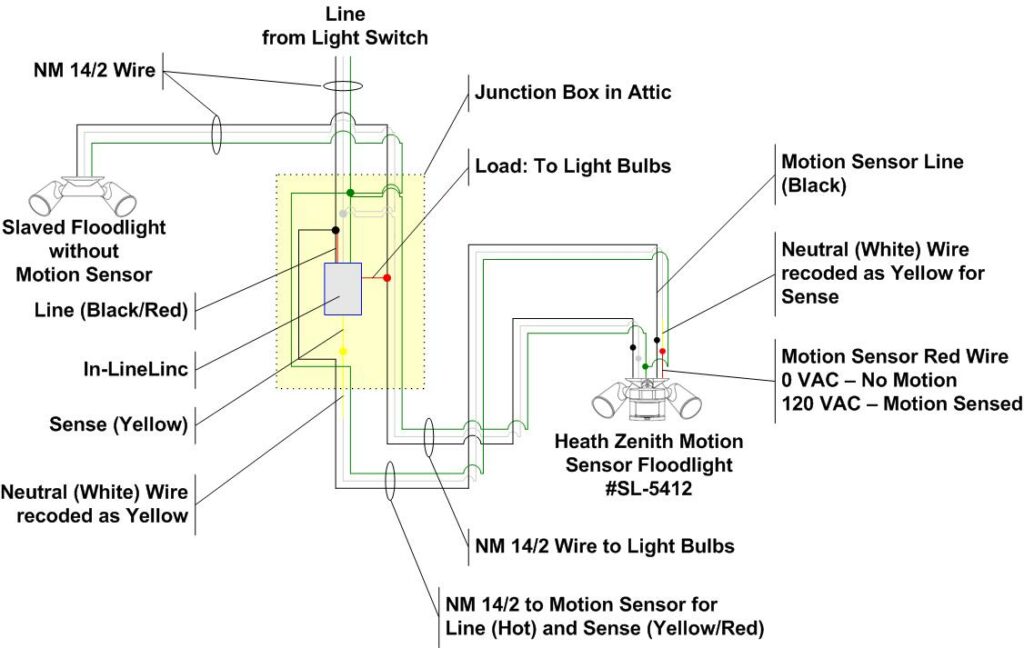
How to Wire Two Floodlights to an In-LineLinc Relay
In a prior articled, I described How to Wire a Motion Activated Floodlight with an Insteon In-LineLinc Relay, which is the simple way to install an In-LineLinc.
The garage installation here is different because I didn’t want to “double up” and use an extra deep junction box for appearances sake; and I wanted to hookup a 2nd floodlight at the other end of the garage as a “slave” unit.
The solution is to run an extra 14/2 NM wire cable from the motion sensor floodlight to the In-LineLinc inside the attic for the “line” (hot) and “sense” (red/yellow) wires. It is helpful to study the above wiring diagram.
Electrical Safety
Working with 120VAC electricity can kill or maim you, burn down the house or deliver an electrical shock that you’ll never forget! If you haven’t studied home electrical wiring, lack a solid knowledge of the electrical building code regulations and don’t know what you are doing, then stop! Hire a professional electrician!
In-LineLinc Relay Installation and Wiring
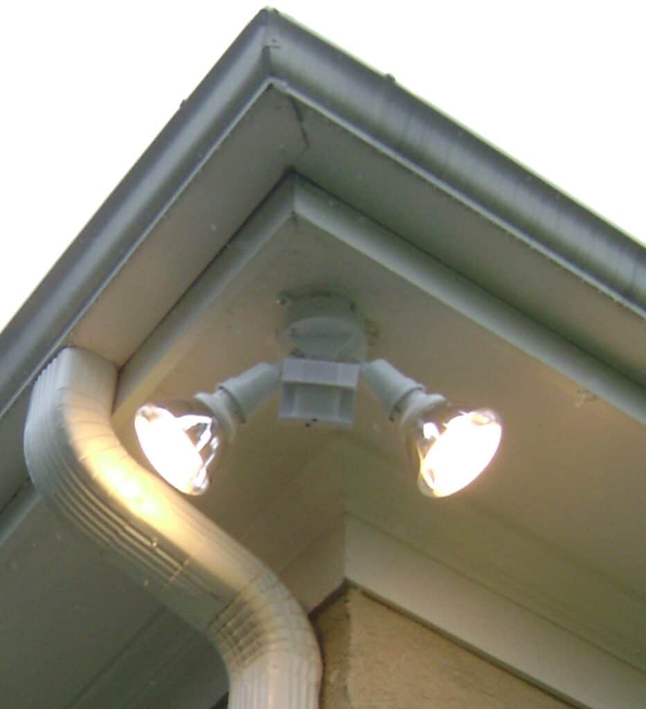
The Heath Zenith #SL-5412 motion sensor floodlight is located at the corner eave of the garage. The floodlight mounted on a white aluminum electrical box that is too shallow to contain the In-LineLinc.
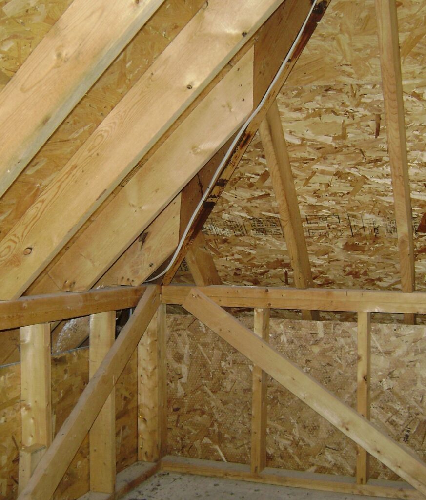
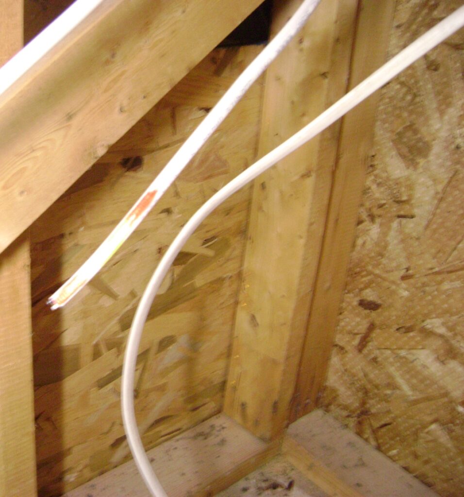
This is the view inside the attic showing the original NM 14/2 wire to the floodlight. The floodlight is controlled by a light switch inside the house. This wire will be rerouted to a new junction box inside the attic.
I began by:
- Shutting off the power to the circuit at the main electrical panel.
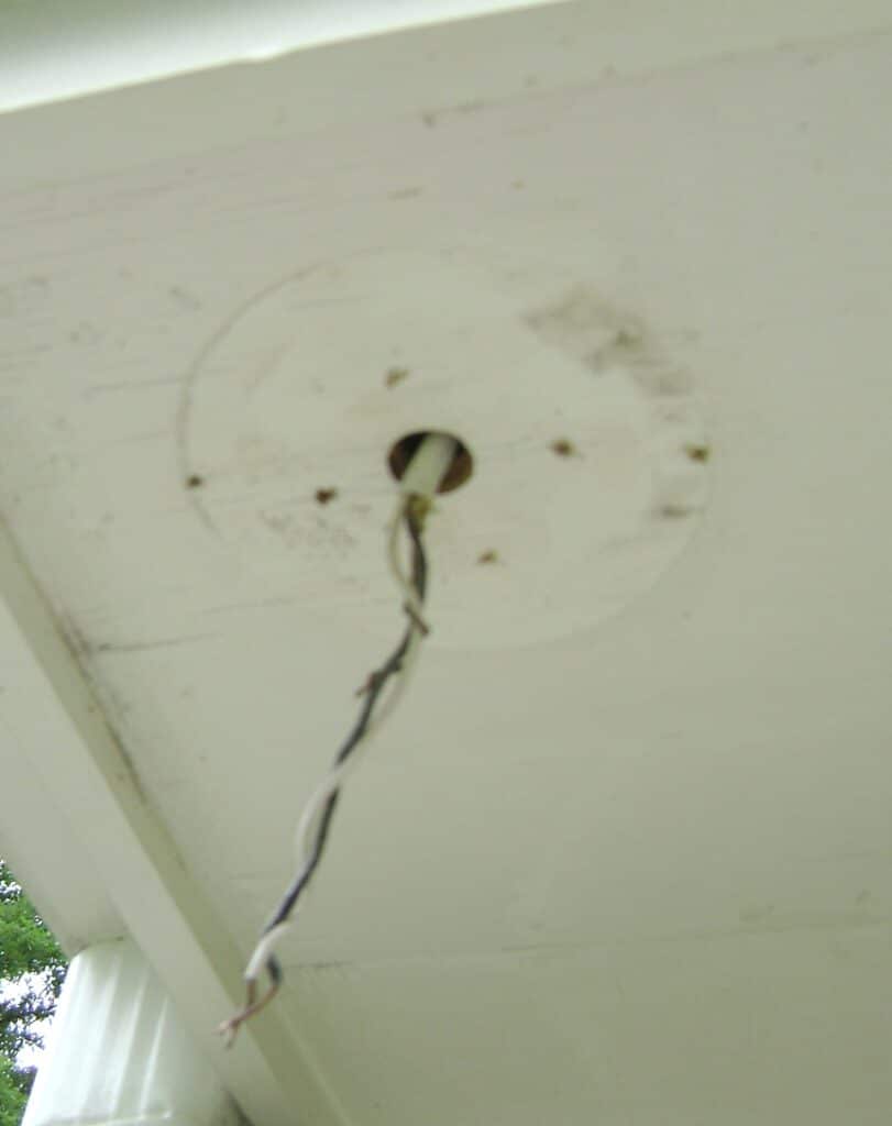
- Removing the floodlight and junction box to expose the original wire as shown below.
- Two (2) new 12 foot long lengths of NM 14/2 were cut, taped to the original wire, and pulled into the attic as the original wire is removed. Before pulling, both ends of one cable was marked with a red pen to identify which cable will be the the load & sense wire (see wiring diagram). You need to mark both ends of the same cable.
The two new NM 14/2 cables are shown after pulling into the attic. Note the red identification mark on the cable to be used for the motion sensor line/sense wires.
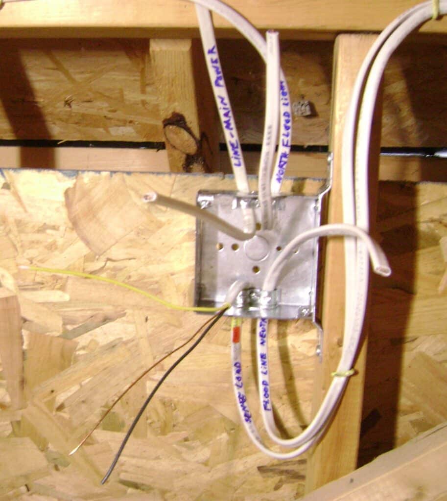
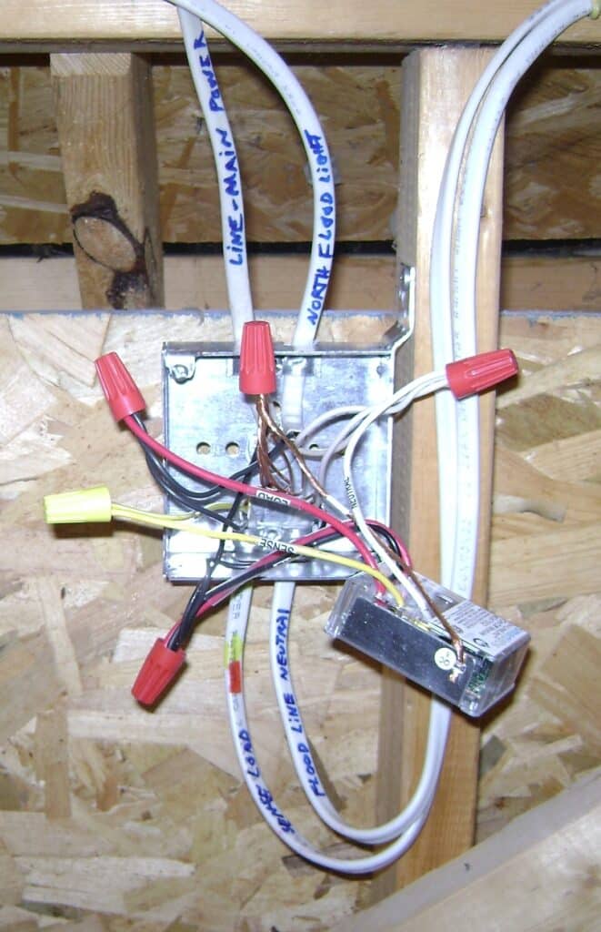
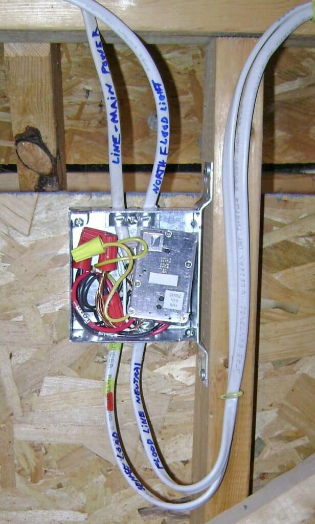
The four cables are brought into a newly installed electrical junction box as shown. Each cable is identified with a permanent marker. Note the neutral (white) wire for the of the load/sense cable has been recoded as yellow (lower left) using a permanent marker. This yellow wire will connect to the sense wire of the In-LineLinc, the other end of this wire will be connected the motion sensor red wire.
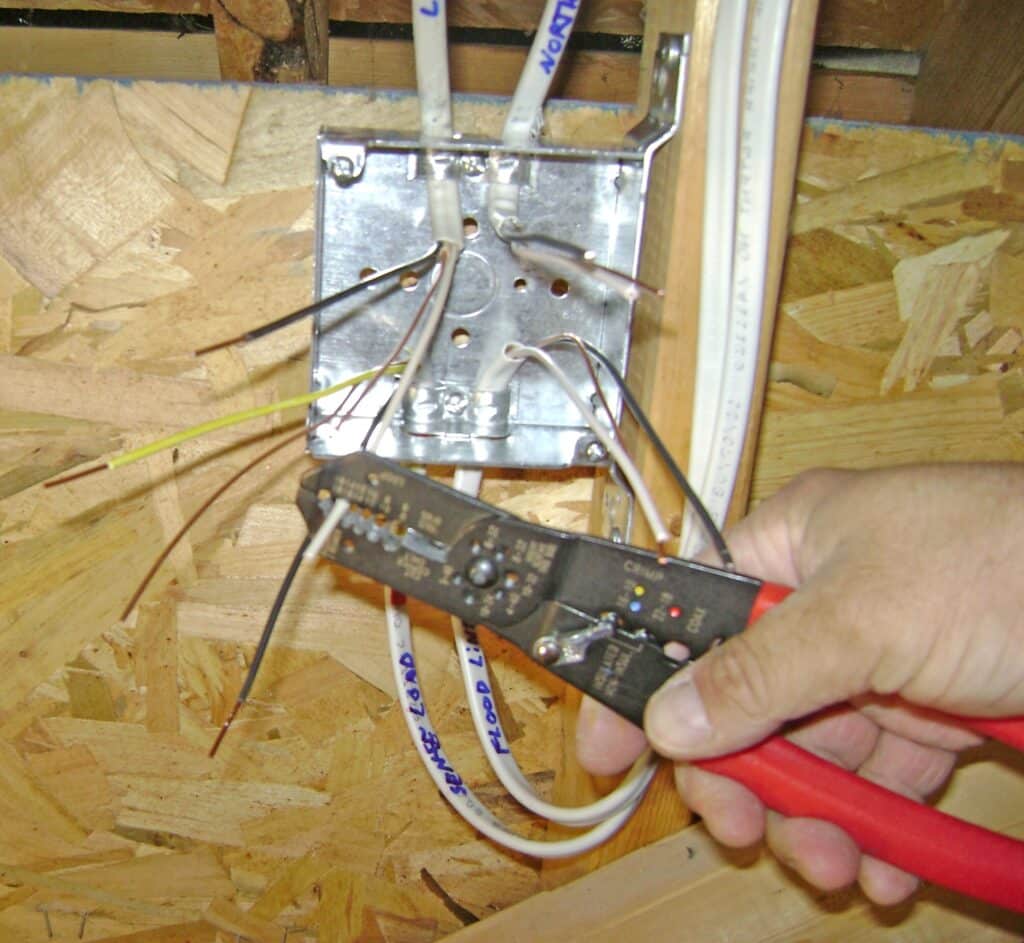
The wires are sorted and stripped as shown:
The junction box wiring for the In-LineLinc, motion floodlight and slave floodlight is complete. The wires enter the junction box from top and bottom in the same arrangement as shown in the wiring diagram. Note that the red load wire of the In-LineLinc is connected to the lamps in both floodlights. The In-LineLinc is rated to 480 watts and my lights use a total of four (4) 26 watt compact fluorescent bulbs for a total load of only 104 watts.
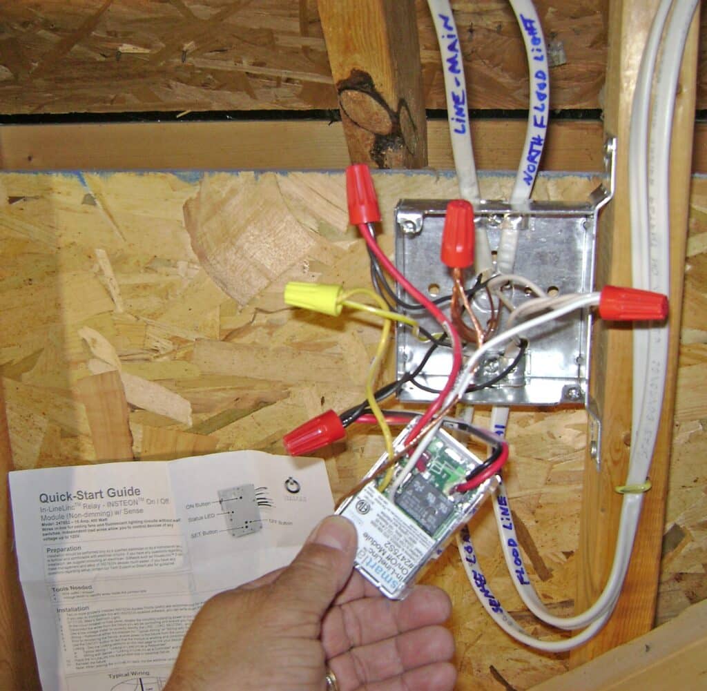
Here’s another view of the In-LineLinc wiring:
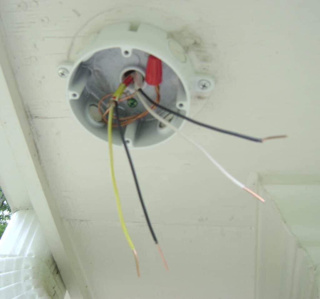
Floodlight Wiring
Two (2) new runs of NM 14/2 electrical cable enter the floodlight junction box as shown. Note the red/yellow marking on the line/sense cable that was made before the new cables were pulled into the attic. The white (neutral) wire has been recoded yellow here as well with a permanent marker to correspond with recoded yellow end inside the attic.
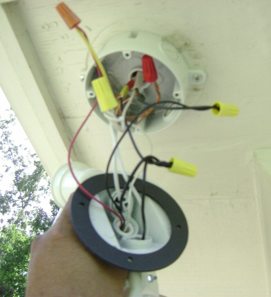
The floodlight is wired and mounted to the outlet box. Note the floodlight red (motion sense) wire is connected to the yellow (sense) wire that feeds to the yellow (sense) input of the In-LineLinc inside the attic. Refer to the wiring diagram for details.
In-LineLinc Final Installation and Testing
The circuit breaker is turned back on (make sure the light switch is on, too!) and the In-LineLinc and floodlights tested for correct operation. My testing consided of:
- Manually turning ON/OFF the floodlight via the small buttons on the face of the In-LineLinc.
- Remotely turning ON/OFF the floodlight via the ISY-99i Admin Console.
- Putting the motion sensor in Test Mode and walking around.
Everything tested A-OK!
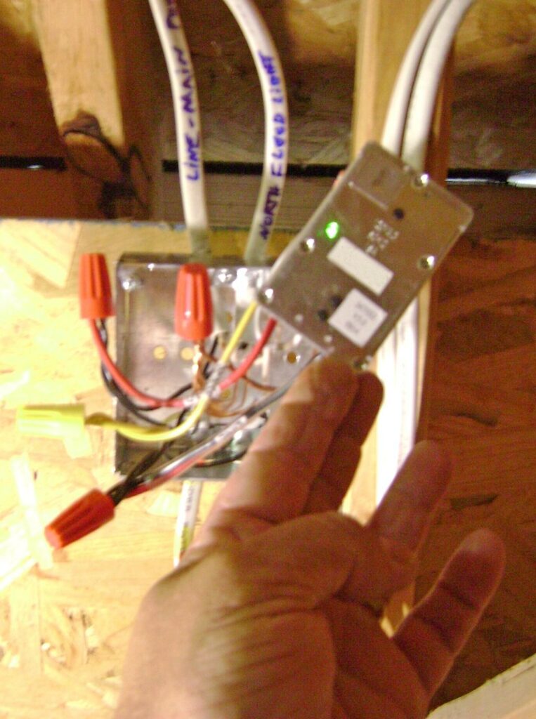
The wires and In-LineLinc are carefully packed inside the electrical junction box.
The metal junction box cover is fastened with two screws. Take care that the In-LineLinc buttons are not touching the box cover!
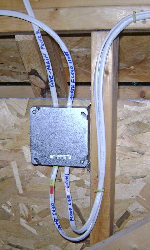
Here’s how the new junction box and cables are arranged. Click for a larger image.
Next Steps
Now I’m ready to do fun things like linking with other Insteon devices, create scenes for coordinated lighting and ISY-99i programs.
Take Care,
Bob Jackson