This project explains how to extend power from an existing wall outlet with Wiremold® surface mount raceway and wire the electrical boxes in this installment of How To Build a Basement Closet. This project is continued from wiring the light switch.
How to Extend Power from an Existing Wall Outlet
At this point in the basement closet project, I’ve completed the Wiremold wiring rough-in and connected the wires for the closet ceiling light and light switch as I work my from the ceiling light back to the existing wall outlet. In other words, I’m making the wiring connections starting at the new electrical circuit termination (the ceiling light) and working sequentially back to circuit origin (the wall outlet). Making the wiring connections in this order minimizes the risk of accidentally working on a live wire because the wall outlet power source is the final connection.
Electrical Safety: As always, the power must be shutoff at the circuit breaker before working on the electrical wiring. Verify the electricity is off with a voltage detector. Hire a licensed electrician if in doubt.
The electrical wiring connections to made next are the:
- Wiremold BW35 junction box.
The outlet box is used here as a junction box here with a blank cover plate. - Leviton T5015-W single receptacle wall outlet and Wiremold BW35 outlet box.
The Wiremold wiring diagram is illustrated here:
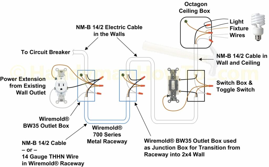
Wiremold Junction Box Wiring
The Wiremold BW35 junction box is used to connect the NM-B 14/2 cable inside the 2×4 stud wall to NM-B 14/2 cable from the Wiremold® 700 Series metal channel. The BW35 box is removed to expose the back plate. Do the following:
- Cut an 6 inch length of NM-B 14/2 cable from the roll and remove the copper ground wire.
- Install a #10 green ground screw in the dimple of the back plate.
- Make a small loop in the end of the ground wire, loop it around the ground screw, then pinch the loop closed with needle nose pliers.
See the red arrow in the next photo. - Tighten the ground screw.
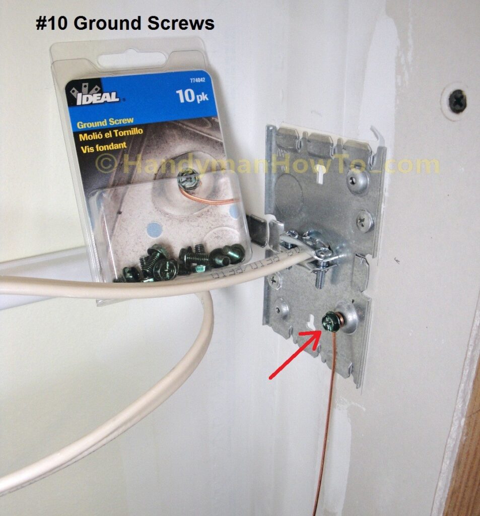
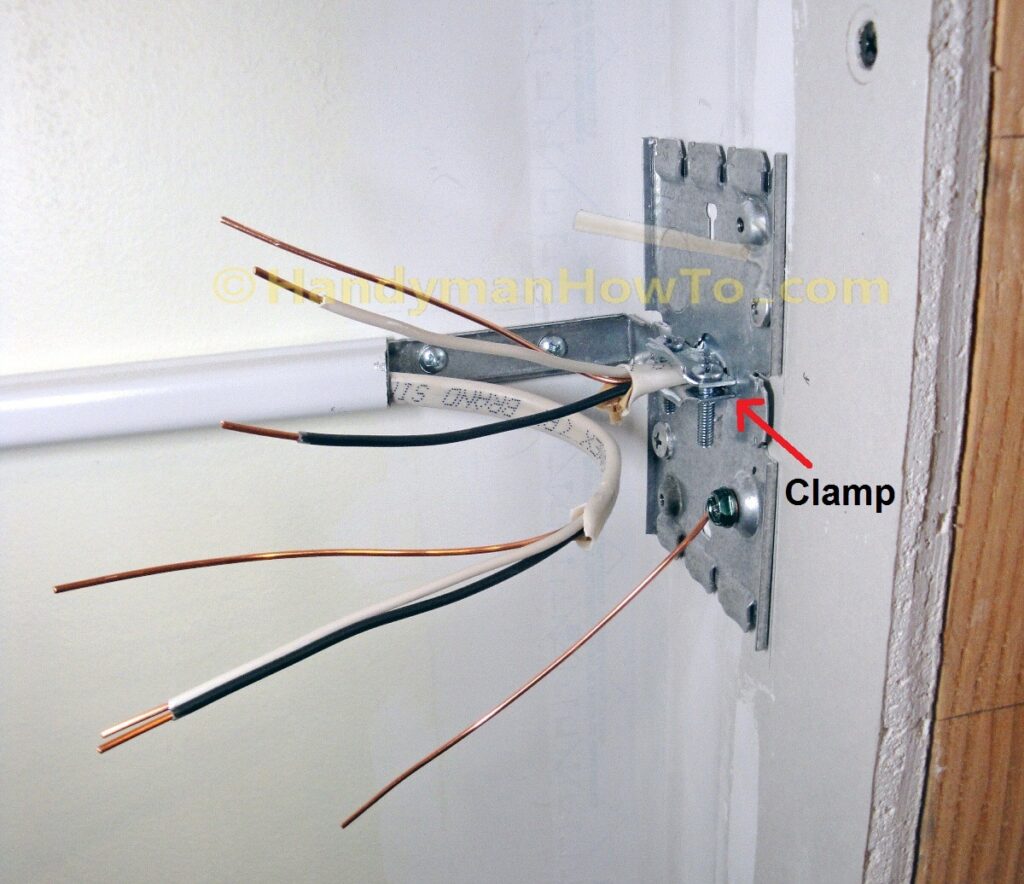
NM-B 14/2 wiring preparation:
- The outer jacket of the NM-B 14/2 cables are carefully removed so as not to damage the insulation on the individual wires.
Make a short, shallow lengthwise cut in the outer jacket at the end of the cable, then peel the outer jacket back like a banana. - Leave 1 inch of of the outer insulation jacket extending past the Halex 3/8 in. 2-Piece Clamp Connector (red arrow in next photo).
Also take care to have 1 inch of the outer jacket insulation for the other cable extending past the Wiremold 90° elbow into the BW35 junction box. - Tighten the cable clamp screws to secure the NM-B 14/2 cable in the center of the back plate.
- Trim the wires if needed to have at least 6 inches of wire extending past the back plate.
- Strip approx. 5/8 inch of insulation from the ends of the black (hot) and white (neutral) wires with wire strippers.
Matching the wire colors, right-twist (clockwise) the ends of the ground, black (hot) and white (neutral) wires together using linesmans pliers and secure each set of wires with a wire nut.
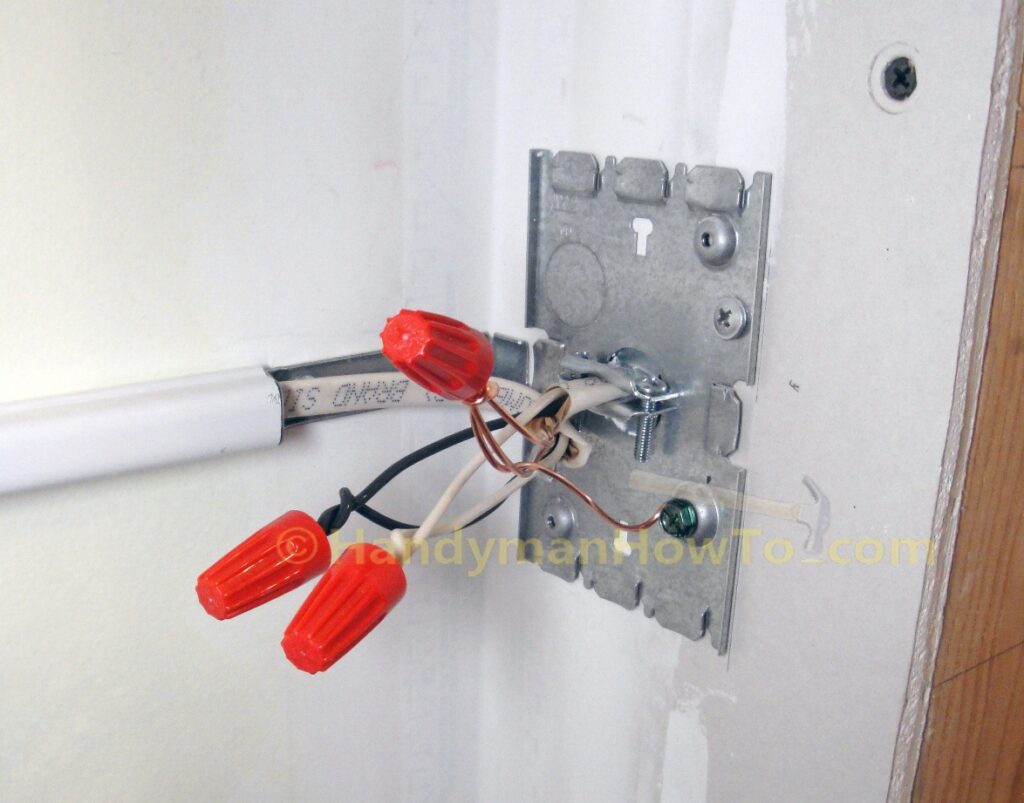
Fold the wires and install the Wiremold BW35 junction box with the two included screws. The junction box will be closed with a standard blank wall plate cover to conceal and protect the wires.
Then snap the elbow cover into place:
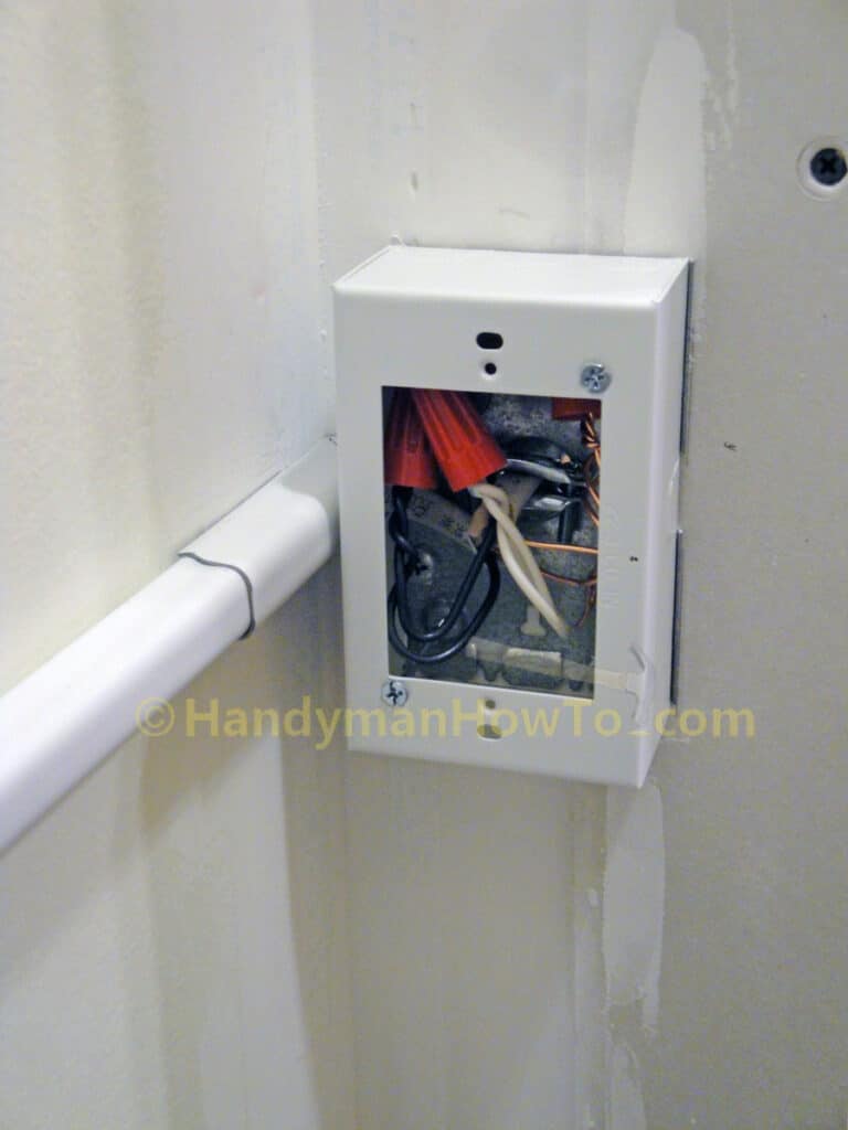
Wiremold Wall Outlet Wiring
Electrical Safety Caution:
The final wiring connections to power the new circuit are about to made. Be absolutely certain to shutoff the power at the circuit breaker panel if you haven’t already done so. Verify the electricity is Off on all wires with a voltage detector to avoid shock, injury or death.
The final wiring steps are to:
- Cut a length 6 inch length of NM-B 14/2 cable from the roll for the new receptacle pigtail wiring.
- Twist and wire nut the NM-B 14/2 wires from inside the wall (to the circuit breaker), the Wiremold raceway and the outlet pigtail.
- Connect the pigtail wires to the new outlet.
The wiring diagram for the following steps is:
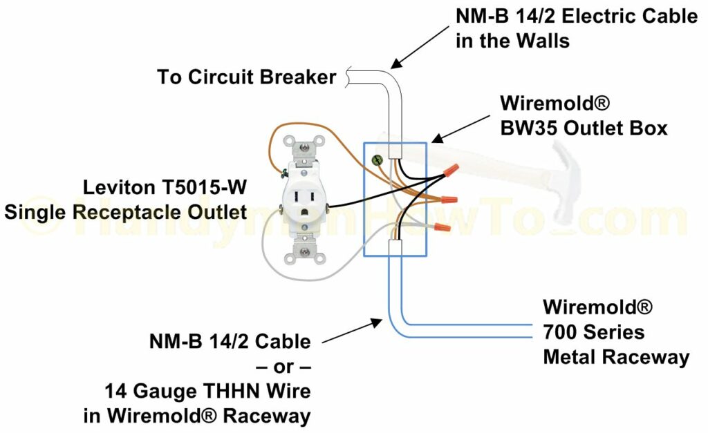
After shutting off power at the circuit breaker and verifying the electricity is indeed Off, I connected the main circuit wires as was done for the junction box (see above). Next, the new single receptacle outlet will be connected to the pigtail wires. Reminder, you can install a dual outlet receptacle if preferred.
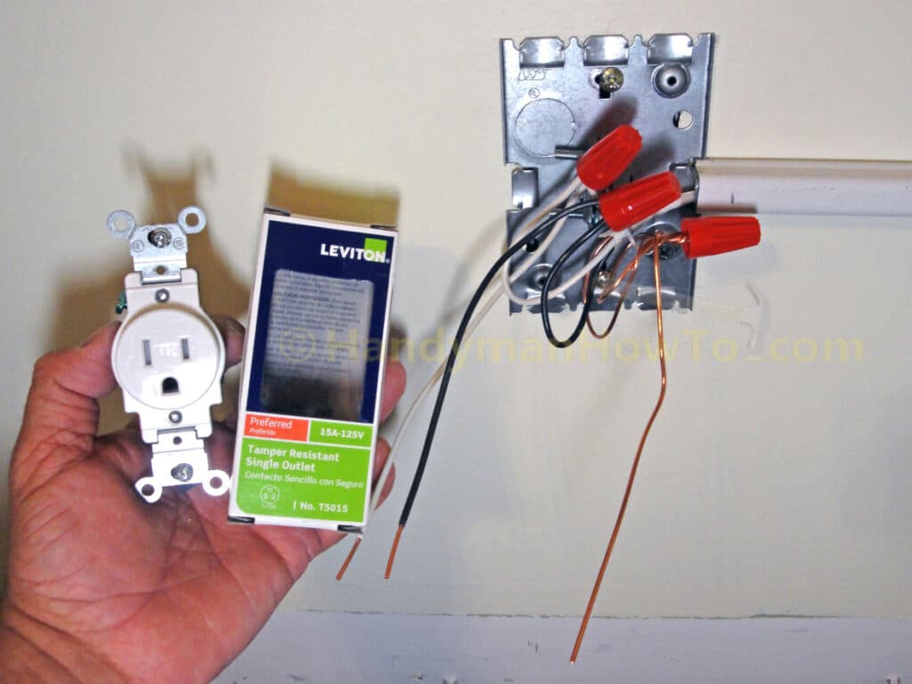
The next (non-standard) installation steps are:
- Wire the new outlet per the manufacturer’s instructions included with the outlet.
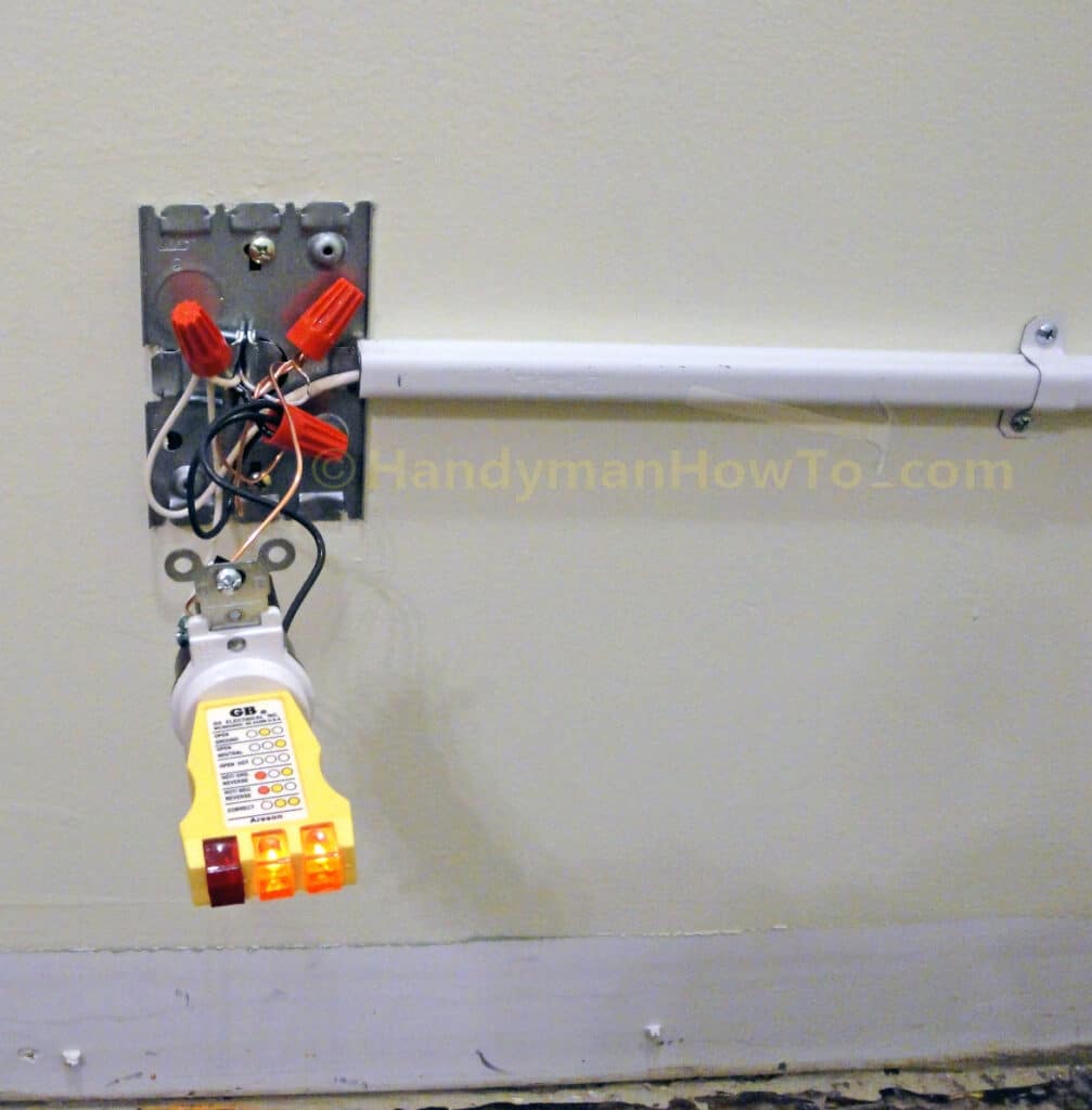
- Insert a receptacle tester into the outlet.
- Turn On the electricity at the circuit breaker to verify my wiring connections (see the photo below).
Two yellow lights indicates the outlet is correctly wired.
Caution: Do not touch the receptacle because the side terminal screws are exposed and you can be shocked!
This is a construction zone and the outlet will be exposed only for a short time. I also don’t have children or pets running about.
You should adhere to the standard outlet installation procedure:
- The electricity is Off at the circuit breaker
- Mount Wiremold metal box to the back plate
- Wire the receptacle per the manufacturer’s instructions
- Mount the outlet to the Wiremold box (the outlet is now protected in the box)
- Turn On the circuit breaker
- Insert the receptacle tester in the outlet to verify the wiring is correct.
I chose not to follow the standard procedure because the wires inside wall were so short and it would be far easier to fix any wiring problems with the box out of the way.
Being careful not to touch the side terminals of the toggle switch, I flipped the light switch On. Let there be light! The new circuit for the closet ceiling light works!
I shutoff the power at the circuit breaker panel, verified the electricity was Off by observing all lights on the receptacle tester are now off (the receptacle tester was still plugged into the outlet), then:
- Fed the wired receptacle through the Wiremold outlet box.
- Mounted the box to the back plate with the two screws included with the Wiremold outlet box.
- Mounted the outlet to the Wiremold outlet box.
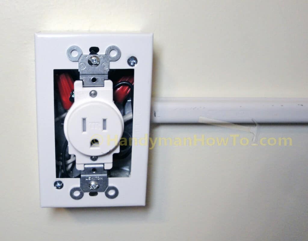
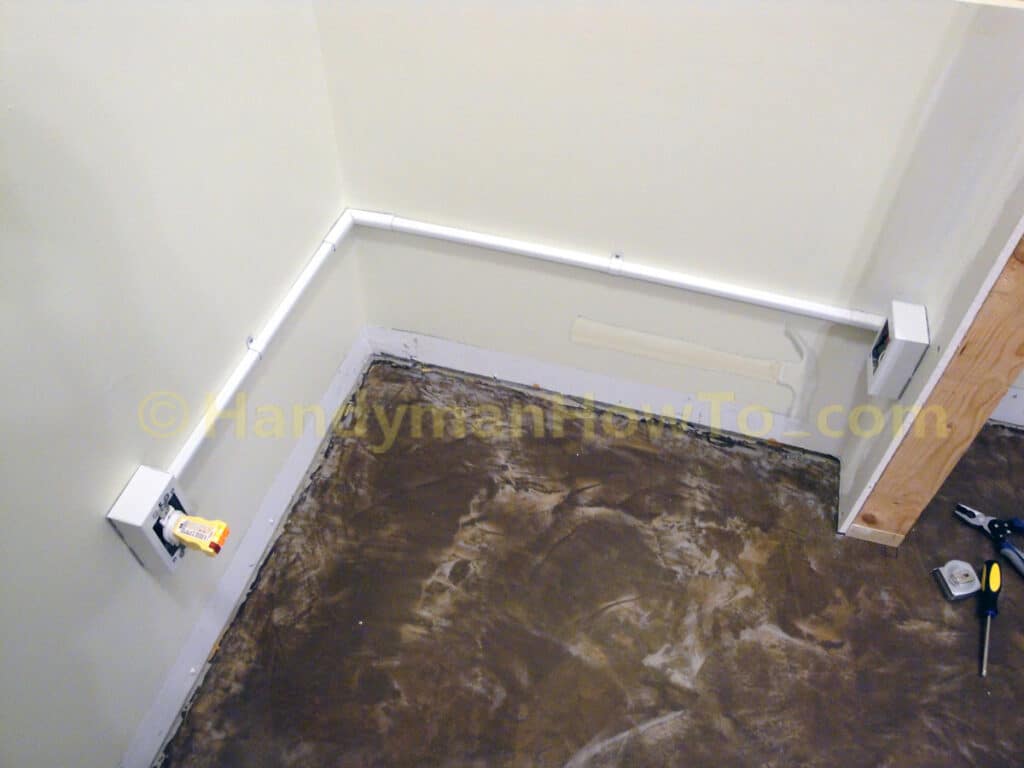
The Wiremold outlet box, metal raceway and junction box to extend power from the existing wall outlet to the ceiling light:
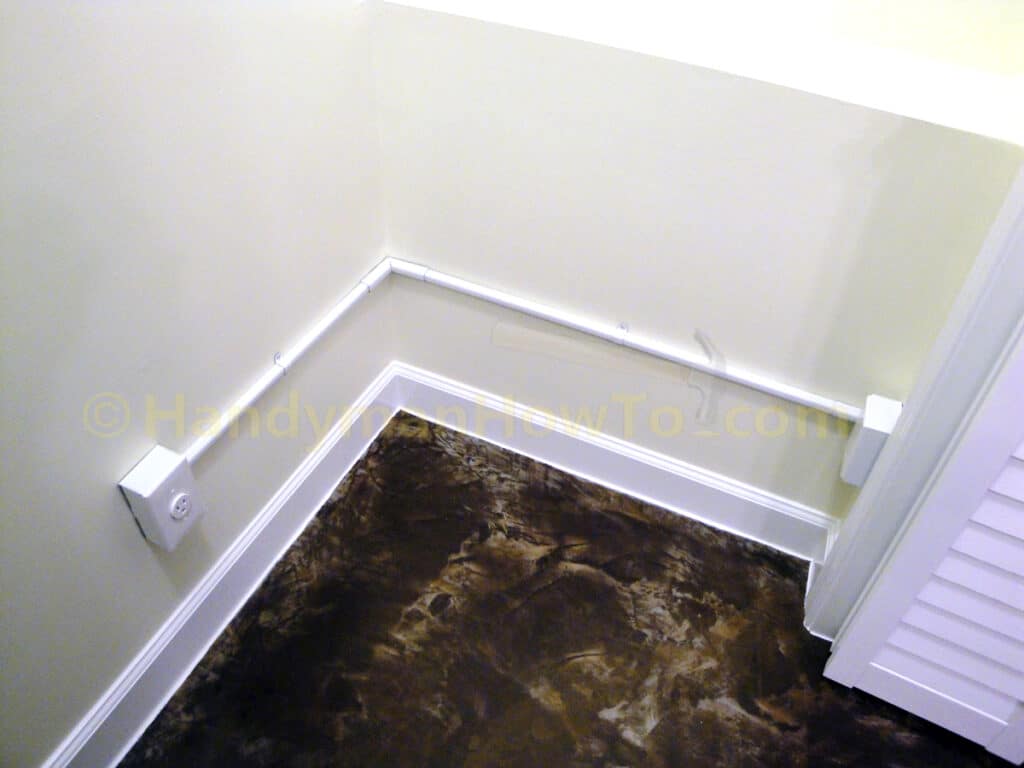
Looking ahead for a moment, here’s the Wiremold wall outlet power extension after the basement closet construction is completed:
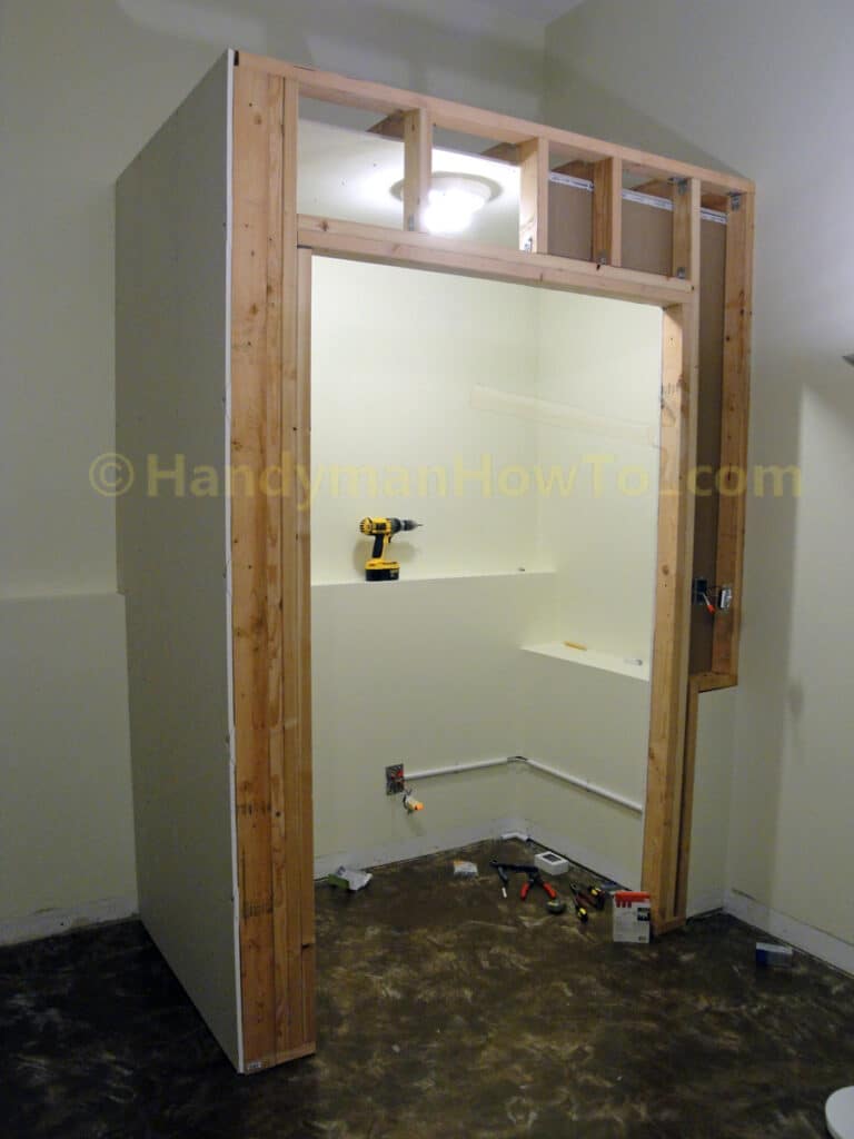
View of the basement closet construction and wiring for the ceiling light:
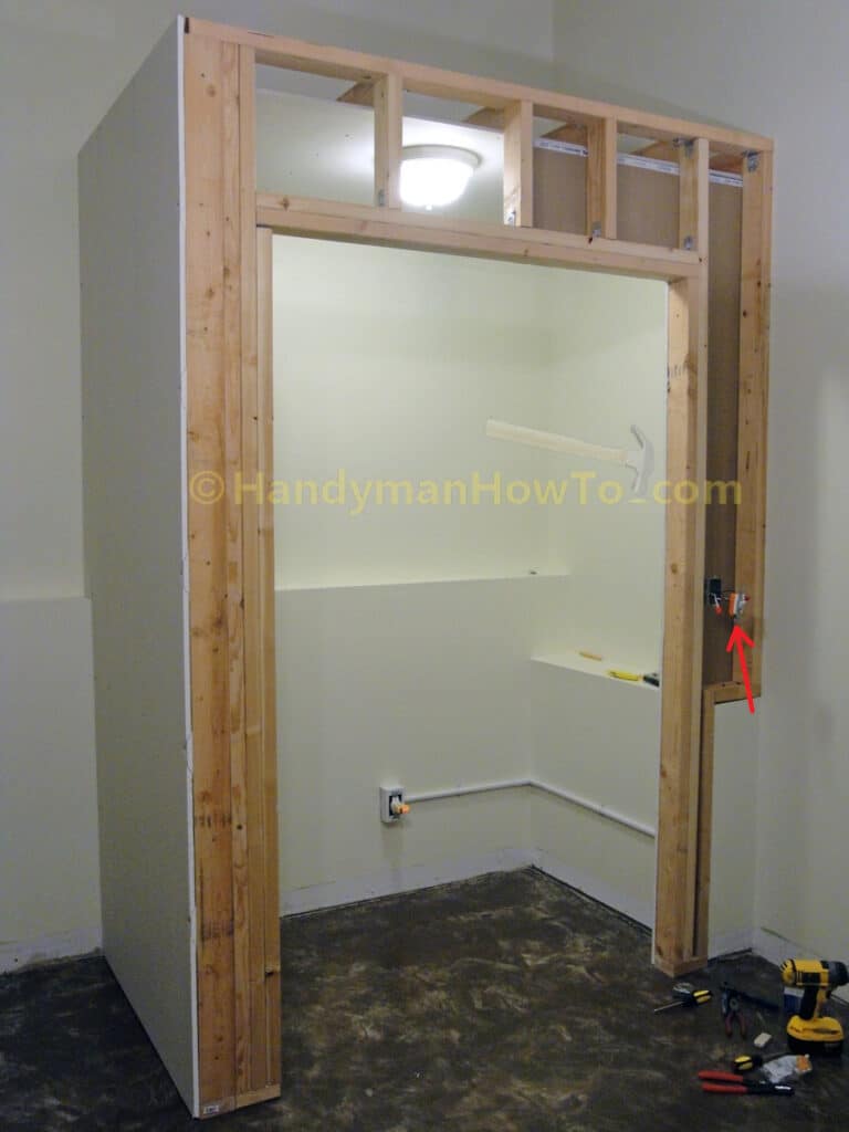
While the circuit breaker Off, I wrapped the toggle switch for the ceiling light with 3M vinyl electricians tape (red arrow in the above photo) to temporarily insulate the side screws because I plan to install that section of drywall after the building inspector has signed-off on my electrical permit.
The drywall and corner bead are installed in the next part of this project.
Hope this helps,
Bob Jackson