The hardwired smoke alarms were never connected to an AC power circuit. A new metal junction box is installed and the existing smoke alarms are wired to a continuous non-switched circuit for power. The new smoke alarms are then wired and installed.
This project is continued from How to Install a Hardwired Smoke Alarm – Part 1.
How to Install a Hardwired Smoke Alarm
The smoke alarms in my house are 10 years old and will be replaced with new Kidde/Firex® Dual Sensor (Ionization and Photoelectric) 120VAC powered hardwired alarms with battery backup. I chose the Consumer Reports #1 rated Kidde PI2010 alarm that sells for about $30. See the PI2010 User Manual for detailed installation and operation instructions:
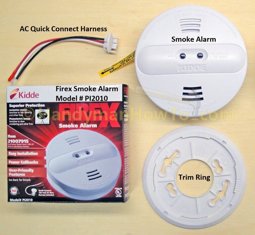
The alarm includes the 9 volt battery – a nice touch to get started.
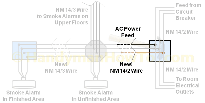
Hardwired Smoke Alarm Wiring Diagram
In How to Install a Hardwired Smoke Alarm – Part 1 I described how the smoke alarm in the finished basement was disabled and improperly concealed in a ceiling crawl space in violation of the Building Codes. The scope of work for this project is to:
- Remove the old smoke detector and ceiling electrical box.
- Wire and install a new smoke detectors in both the finished and unfinished sections of the basement.
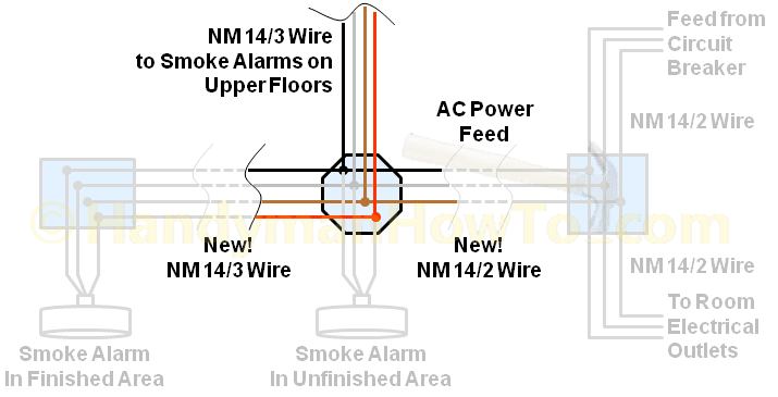
120VAC power for the smoke alarms will provided by a new branch circuit from an existing junction box on a continuous (i.e. non-switched) circuit. The new work is indicated by the green box in this wiring diagram:
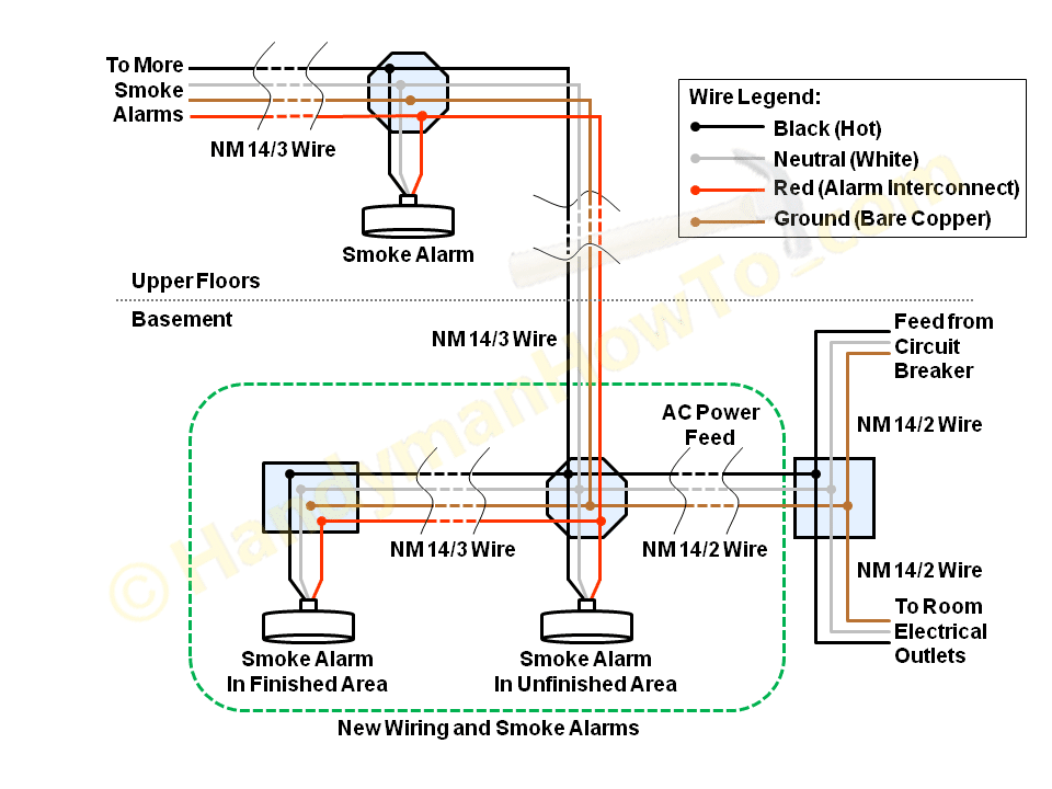
The smoke detectors are hardwired as follows:
- 120VAC power is provided by the hot (black) and neutral (white) wires.
- Interconnect alarm signaling is carried by the red wire. If one alarm is triggered, it will signal the other alarms to sound.
- The neutral (bare copper) wire is not used by the smoke alarms and no connection is required. However, I connect the ground wires between the different cable runs as a matter of personal preference. A continuous ground wire is your friend in safety.
If you’re not comfortable and experienced working with 120VAC wiring, I strongly recommend hiring a licensed electrician.
Smoke Alarm Placement
The National Fire Protection Association (NFPA) and the Kidde PI2010 Smoke Alarm Users Manual provide detailed guidance on where to install smoke alarms. In brief, smoke alarms should be installed:
- On every level of the home, including the basement.
- On the ceiling if possible, at least 4 inches away from the wall.
- Outside of every bedroom on older homes to comply with the old rules.
- New homes must have a smoke alarm in every bedroom and all smoke alarms must be interconnected.
Do not install smoke alarms:
- Near windows, doors and heating/cooling vents because drafts can interfere with the detector.
- In the attic.
- In crawlspaces.
Smoke Alarm Installation Tools
The following tools were needed to wire and install the smoke alarms, moving clockwise from the top these are:
- Drywall jab saw
- Cordless drill/driver
- Needle nose pliers with cutter
- Wire stripper / cutter
- Utility knife
- Non-contact voltage detector

Smoke Alarm Wiring: NM-B 14/3 versus NM-B 14/2 Cable
Before I begin wiring the new smoke alarm, I’ll take a moment to explain the two types of electrical cable that I’ll be using.
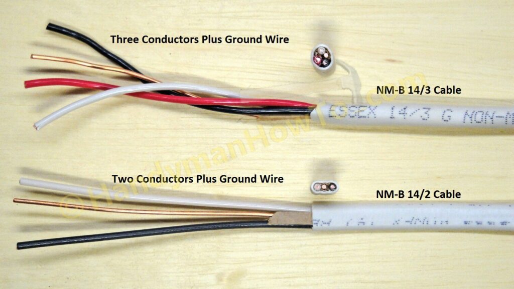
NM-B 14/3 wire means Non-Metallic 14 gauge, 3 conductor plus ground. The ‘B‘ designates the application – for exposed or concealed work in normally dry locations such as inside the home. The conductors are:
- Hot (black) or line side.
- Neutral (white).
- Red – used here for alarm interconnect signaling, so if one alarm goes off, they all sound.
plus the bare copper ground wire. The smoke detectors are ungrounded and the ground wire is not used.
NM-B 14/2 is a 14 gauge, 2 conductor plus ground wire. Two conductors are:
- Hot (black) or line side.
- Neutral (white).
I used NM-B 14/2 wire to run a new AC branch feeder circuit to power the alarms (see the junction box at the far right of the above wiring diagram).
In this project, I’ll use the terms “wire” and “cable” somewhat interchangeably. Strictly speaking, “cable” refers to the entire NM-B wire bundle with the outer insulation jack where “wire” refers to an individual conductor within the cable.
Unfinished Basement Smoke Alarm Installation
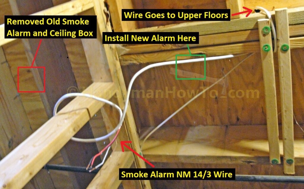
I began by removing the old smoke alarm and ceiling box from the crawlspace above the finished basement; recall that I determined after careful analysis there is no AC power on the alarm circuits. The new smoke alarm will be located nearby in the unfinished area of the basement where the gas furnace, gas water heater and my workshop are located. The new position is only about 5 feet away but in a much more accessible location. I’ll reuse the existing NM-B 14/3 cable that interconnects to the the other smoke alarms in the home:
Smoke Alarm Ceiling Junction Box Wiring
An octagon ceiling box is installed on the floor joist to wire in the new smoke alarm. The existing NM 14/3 alarm wire from the upper floors is brought in on the left and new cables are brought in on the right side: NM-B 14/2 for power and NM-B 14/3 for the second smoke alarm to be installed in the finished basement area. Remember the red wire in the NM-B 14/3 cable is needed for the smoke alarm signaling interconnection.
Note: The smoke alarm trim plate will not fit a 4″ square junction box, you must use an octagonal or rectangular ceiling box. I chose the deep octagon box because it can handle four cables without exceeding the box fill capacity per the National Electrical Code (NEC):
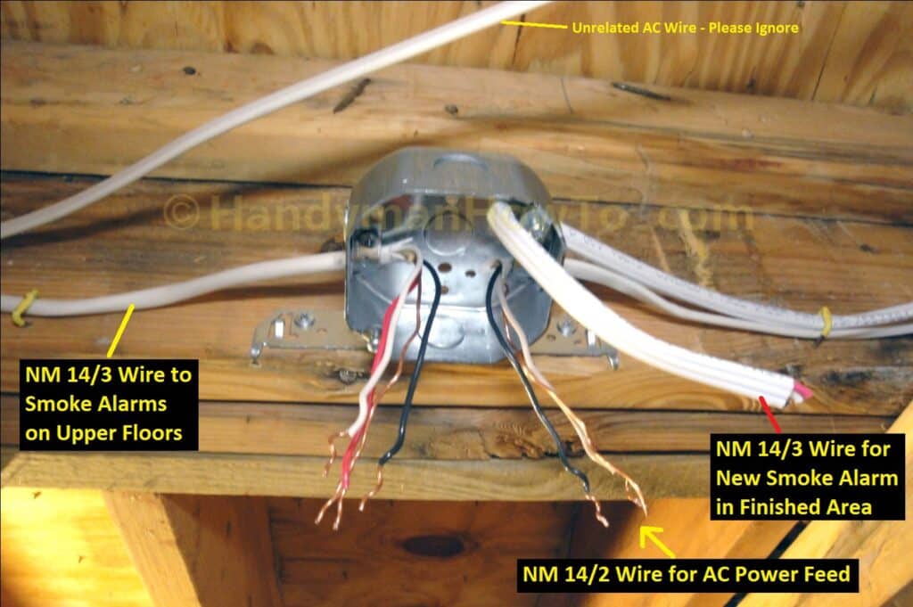
The above photo corresponds to these cables in the wiring diagram:
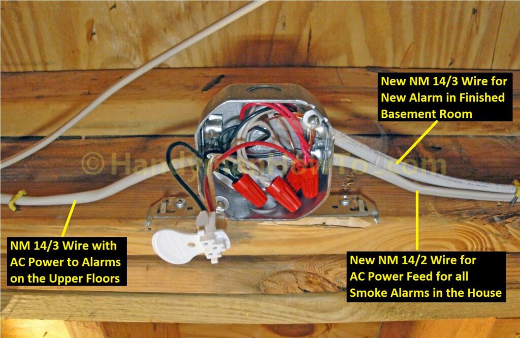
5/8 inch of insulation is stripped from the wires, then the wires are matched by color, right-twisted (clockwise) together and secured by a wire nut to the Kidde PI2010 AC Quick Connect Harness. A #10-32 green ground screw and ground wire pigtail is fastened to the junction box, then twisted and nutted with the other ground wires. Metal junction boxes must be grounded per NEC 250.148 (C).
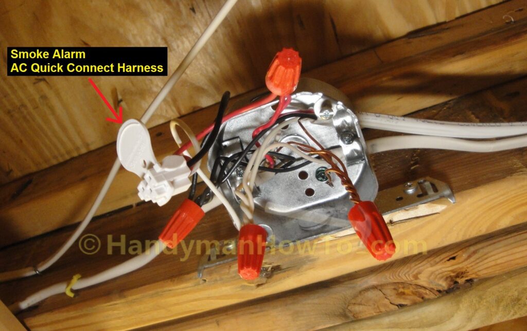
The wires are tucked into the ceiling box with the AC Quick Connect hanging down as shown:
The AC Quick Connect pigtail is inserted through the trim plate, the trim plate fastened to the octagonal ceiling box with two screws (included with the ceiling box) and the AC Quick Connect plugged into the smoke alarm.
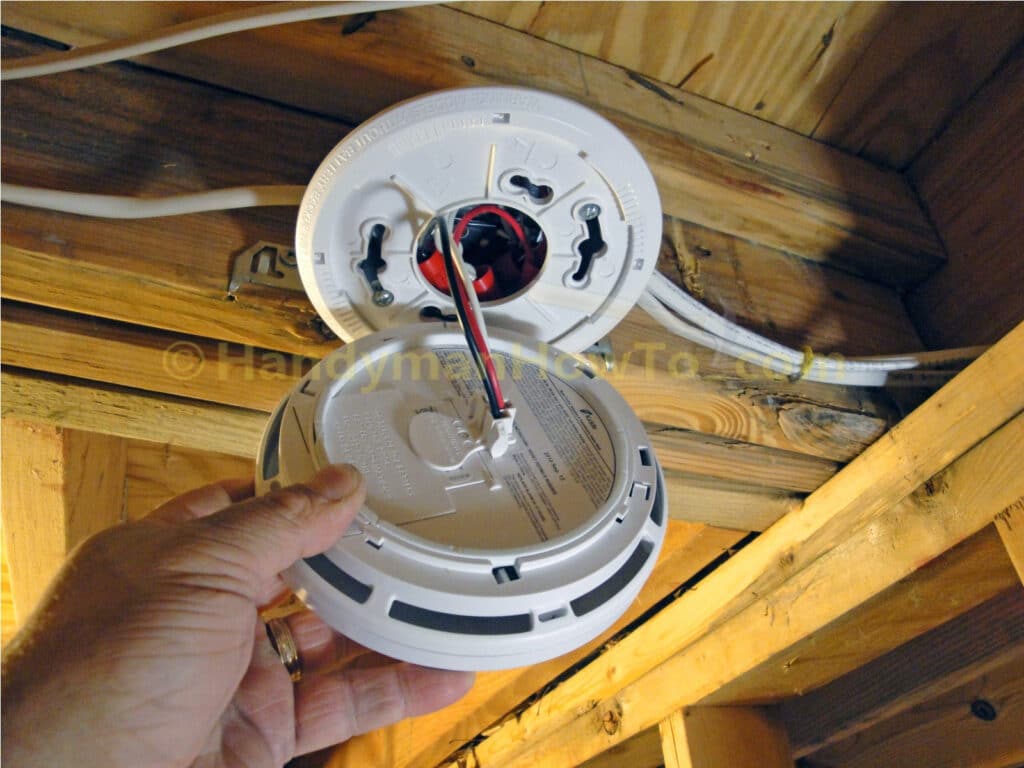
The smoke alarm is mounted to the trim plate by twisting on until it ratchets into place.
120VAC Branch Circuit Smoke Alarm Wiring
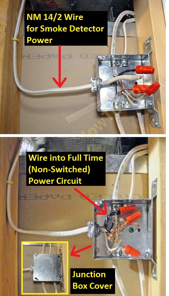
A new run of NM-B 14/2 cable is installed between the octagonal ceiling box and a convenient junction box on the wall about 10 feet away. The junction box is on a circuit that is connected at the main electrical panel. It’s extremely important the smoke alarms are on a continuous non-switched circuit and not to a light switch.
The new circuit for the non-switched (or full time) AC power is highlighted in the wiring diagram:
Electrical Safety: Be certain to shutoff the electricity at circuit breaker or fuse box. Confirm the circuit is dead with the voltage detector to prevent shock, burns, fire and/or death.
The new NM-B 14/2 cable run for the smoke alarm power feed is routed to an existing junction box and wired. Remember to secure your new cable with insulated cable staples within 1 foot of the junction box and every 4 or 5 feet along the floor joists or 2×4 wall studs:
If you don’t have a convenient junction box to splice into, you can splice into an existing circuit as explained in this project.
Jumping ahead for perspective, I’ve installed the 2nd smoke detector in the next photo. The green AC power indicator glows when the alarm is on 120VAC power. For now, the circuit breaker and AC power must remain shutoff.
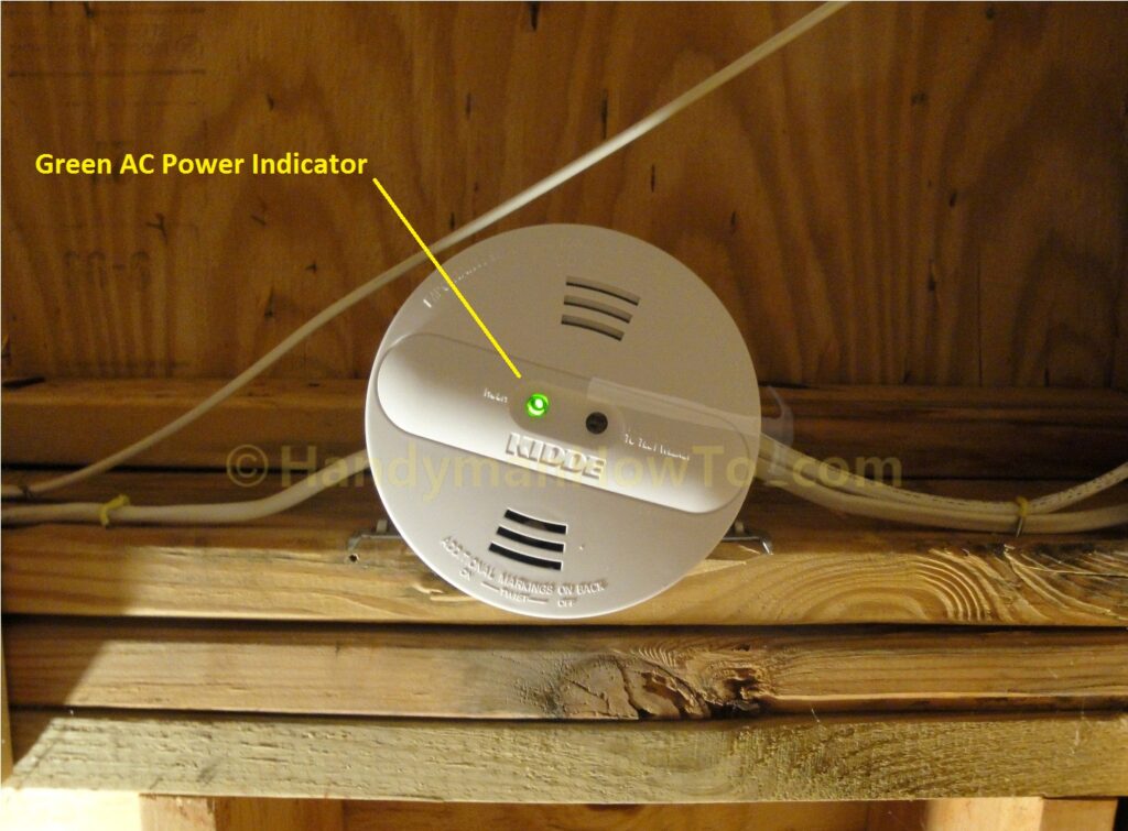
The second smoke detector is installed in a finished basement room in How to Install a Hardwired Smoke Alarm – Part 3.
Thanks for reading,
Bob Jackson